

TACHOMETER CIRCUIT TESTS
Check voltage at the battery. Use this reading as a reference for battery voltage.
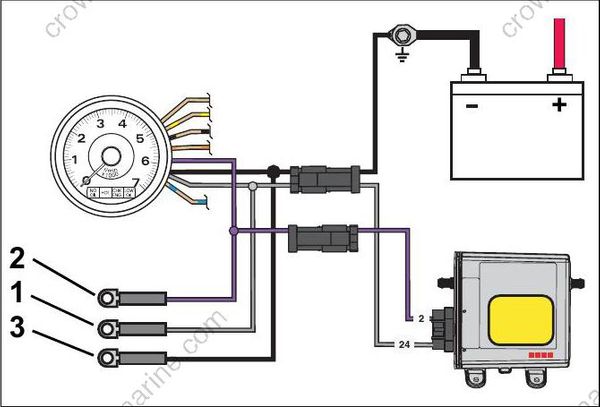
- Purple lead
- Black lead
- Gray lead
Connect the red meter lead to the tachometer purple wire and the black meter lead to the tachometer black wire (key ON, outboard NOT running).
- If meter shows battery voltage, go to next step.
- If meter shows less than battery voltage, check the purple, red/purple, and black wiring circuits; fuse, key switch, and battery connections.
Disconnect gray and black wires at tachometer. Set Fluke 29 Series II meter, or equivalent, to Hz scale. Connect meter between gray wire and black wire. With outboard running at 1000 RPM, meter should indicate 90 to 105 Hz.
- If meter reads 90 to 105 Hz, replace tachometer.
- If meter reads low or no signal, confirm output on gray wire at pin 16 of EMM J1-A connector.
– Reading OK – Check condition of tachometer circuit (gray wire). Repair as needed.
– Reading not OK – Check connection at EMM; replace faulty EMM.
FLYWHEEL AND STATOR SERVICING
IMPORTANT: Weak flywheel magnets can cause low alternator output and affect outboard performance. Weak flywheel magnets can also cause low readings on ignition test equipment, such as a peak-reading voltmeter, which might cause unnecessary parts replacement.
An accurate test of alternator output can help determine the flywheel’s condition. Refer to CHARGING SYSTEM TESTS on p. 121.
Flywheel Removal
To prevent accidental starting while servicing, disconnect the battery cables at battery.
Remove the recoil starter assembly. Refer to RECOIL STARTER REMOVAL on p. 305.
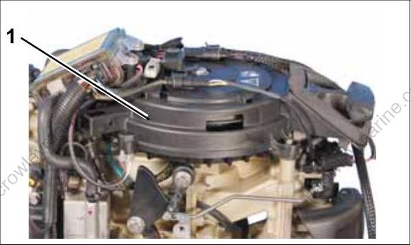
- Recoil Starter
