

STATOR TESTS
The stator consists of 2 windings (6 poles each) on a 5 inch diameter core and generates an out put voltage of 55 VAC (700 watts maximum). This voltage is converted by the Battery Charge Module to provide 12 VDC for battery charging (approximately 8 A at 500 RPM and 15 A from 3000 RPM to WOT) and 55 VDC for fuel injector, and fuel and oil pump operation.
Stator Resistance Tests
Use a digital multimeter to check resistance of stator windings.
Disconnect stator (4-pin) connector from the engine harness (4-pin) connector.
| Yellow & Yellow / white 1.0 ± .020 Ω @ 73°F (23°C) |
|---|
| Brown & Brown / white 1.0 ± .020 Ω @ 73°F (23°C) |
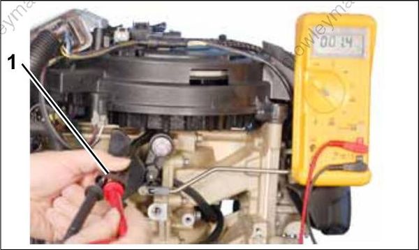
1.Stator connector
Connect meter leads to the following pins:
- Yellow/white and yellow (pins 1 and 2)
- Brown/white and brown (pins 3 and 4)
IMPORTANT: A reading of less than 2 ohms is acceptable. Make sure meter is calibrated to read 1 ohm or less.
To check for a grounded winding, connect one meter lead to ground and alternately connect the other meter lead to each stator wire. Meter should read no continuity. If meter reads continuity, replace stator.
Stator Voltage Output Test
Use a digital multimeter to check stator output voltage. Set meter to read 110 VAC output.
To prevent accidental starting of outboard, disconnect crankshaft position sensor (CPS).
Disconnect CPS.
Disconnect stator (4-pin) connector from the engine harness (4-pin) connector.
Connect Stator Test Adaptor tool, P/N 354719, to stator connector.
Connect meter leads to terminals of adaptor tool. With a fully charged battery, crank outboard (300 RPM minimum) and observe meter reading:
- 55 VAC above 500 RPM
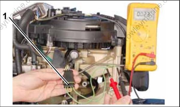
1.Stator Test Adaptor
IMPORTANT: Rope start models can be tested using a Peak Reading Voltmeter, set to the 50 VAC scale. Remove spark plugs and rotate fly wheel with the starter rope, using a long, steady pull. Voltage should be approximately 30 VAC.
