

SENSOR TESTS
All sensor circuits are dependent on wiring and connections, EMM supplied current (5 V), and sensor resistance. The supplied current flows through the wiring circuit and sensor before returning to the EMM.
IMPORTANT: Use Evinrude Diagnostics soft ware to monitor sensor circuit voltages or values.
Crankshaft Position Sensor (CPS) Test
Use the Evinrude Diagnostics software CPS Sync and engine RPM displays to confirm a valid CPS signal while the outboard is cranking or running. An RPM display higher than zero indicates a CPS signal to the EMM.
Remove the electrical connector from its retainer on the recoil starter housing. Disconnect the crankshaft position sensor.
Use a digital multimeter to measure sensor resistance between the yellow and white wires. The complete circuit can be tested by measuring between pins 4 and 12 of the EMM connector.
| Sensor Resistance |
|---|
| 560 Ω ± 10% @ 77°F (25°C) |
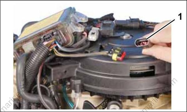
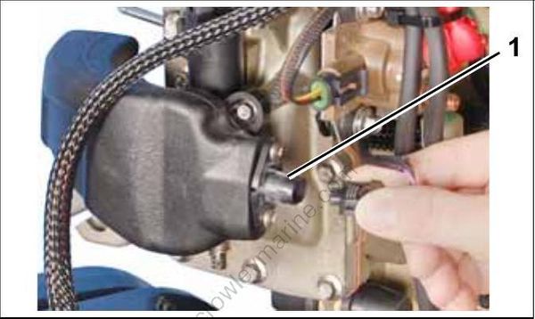
1.CPS Connector
The CPS is mounted to throttle body housing and requires no adjustment. Air gap or clearance to flywheel is fixed at approximately 0.054 in.
(1.37 mm). The acceptable clearance is 0.018 to 0.091 in. (0.45 to 2.38 mm).
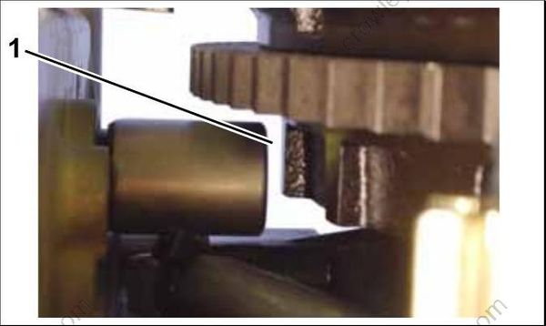
1.CPS gap
Throttle Position Sensor (TPS) Test
Use Evinrude Diagnostics software to monitor TPS voltage while the outboard is running. Volt age should change evenly as sensor lever is moved.
Remove the electrical connector from the throttle position sensor.
Use a digital multimeter to measure sensor resistance.
| Sensor Resistance between “A” and “B” |
|---|
| > 3000 Ω @ 77°F (25°C) |
| Sensor Resistance between “A” and “C” |
|---|
| > 4000 Ω @ 77°F (25°C) |
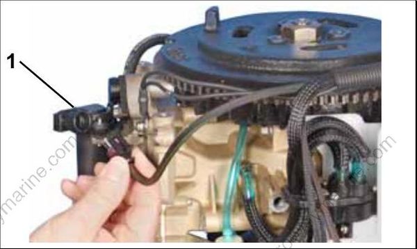
1.TPS
Connect red meter lead to terminal “A” and black meter lead to terminal “C.” Rotate the sensor lever through its range of travel. Resistance reading must change evenly as the sensor lever is moved. Connect red meter lead on terminal “B” and black meter lead to terminal “C.” Rotate the sensor lever. Resistance reading must change evenly as the sensor lever is moved.
Engine Temperature Sensor Test
Remove the electrical connector from the engine temperature sensor.
Use a digital multimeter to measure sensor resistance.
| 680 Ω ± 5% @ 212°F (100°C) |
|---|
| 10000 Ω ± 1% @ 77°F (25°C) |
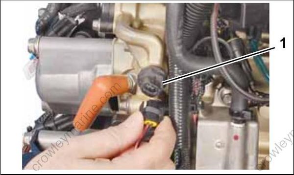
1.Engine temperature sensor
Air Temperature Sensor (AT) Test
Remove the electrical connector from the air temperature sensor.
Use a digital multimeter to measure sensor resistance.
| AT Sensor Resistance |
|---|
| 680 Ω ± 5.25% @ 212°F (100°C) |
| 10000 Ω ± 1.5% @ 77°F (25°C) |
| 32654 Ω ± 3.0% @ 32°F (0°C) |
1.AT sensor
