

TACHOMETER CIRCUIT TESTS
Check voltage at the battery. Use this reading as a reference for battery voltage.
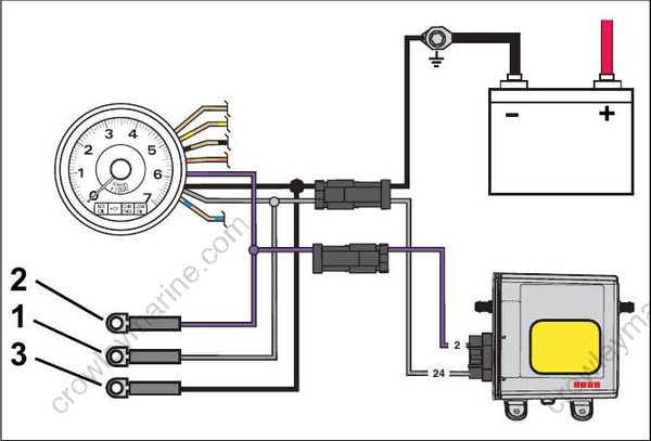
- Purple lead
- Black lead
- Gray lead
Connect the red meter lead to the tachometer purple wire and the black meter lead to the tachometer black wire (key ON, outboard NOT running).
- If meter shows battery voltage, go to next step.
- If meter shows less than battery voltage, check the purple, red/purple, and black wiring circuits; fuse, key switch, and battery connections.
Disconnect gray and black wires at tachometer. Set Fluke 29 Series II meter, or equivalent, to Hz scale. Connect meter between gray wire and black wire. With outboard running at 1000 RPM, meter should indicate 90 to 105 Hz.
- If meter reads 90 to 105 Hz, replace tachometer.
- If meter reads low or no signal, confirm output on gray wire at pin 16 of EMM J1-A connector.
– Reading OK – Check condition of tachometer circuit (gray wire). Repair as needed.
– Reading not OK – Check connection at EMM; replace faulty EMM.
FLYWHEEL AND STATOR SERVICING
IMPORTANT: Weak flywheel magnets can cause low alternator output and affect outboard performance. Weak flywheel magnets can also cause low readings on ignition test equipment, such as a peak-reading voltmeter, which might cause unnecessary parts replacement.
An accurate test of alternator output can help determine the flywheel’s condition. Refer to CHARGING SYSTEM TESTS on p. 121.
Flywheel Removal
To prevent accidental starting while servicing, disconnect the battery
cables at battery.
Remove the recoil starter assembly. Refer to RECOIL STARTER REMOVAL on p. 305.
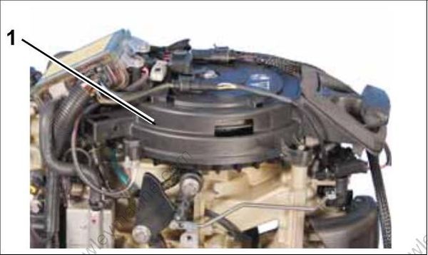
1.Recoil Starter
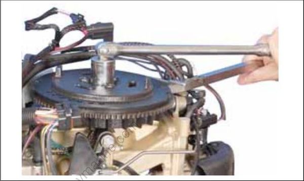
Use Flywheel Holder, P/N 771311, or equivalent, and a 28 mm socket to remove flywheel nut.
Apply Moly Lube grease to the threads of the puller pressing screw, P/N 307637, and the center hole of the crankshaft.
Assemble the following components from Universal Puller Set, P/N 378103:
- Body, P/N 307636
- Screw, P/N 307637
- Handle, P/N 307638
- Three screws P/N 309492
- Three washers, P/N 307640
Put the puller on flywheel with body flat side up. Attach the puller body with the three shoulder screws and washers. Hold puller body with handle, and tighten pressing screw until flywheel releases. Turn the center screw and lift the fly wheel off of the crankshaft.
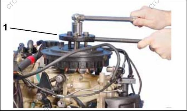
1.Universal puller
Stator Service
Disconnect stator harness connector.
Remove three allen head screws to remove stator.
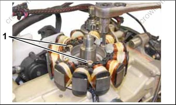
1.Stator screws
To install stator, position stator on cylinder block. Apply Nut Lock to screw threads. Install screws and tighten in crossing pattern to a torque of 84 to 106 in. lbs. (9.5 to 12 N•m).
Flywheel Installation
Install the outer edge of flywheel key parallel with centerline of crankshaft.
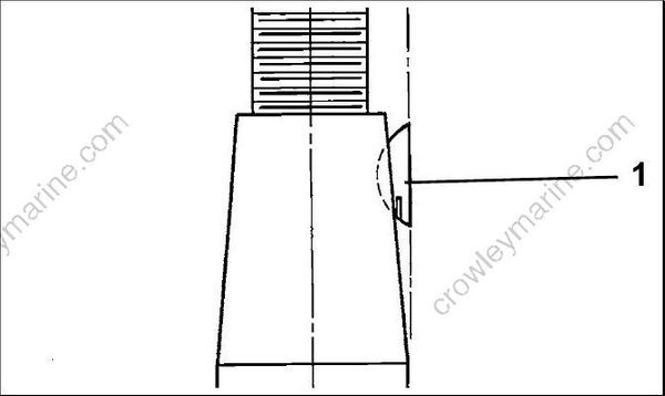
1.Flywheel key
Thoroughly clean the crankshaft and flywheel tapers with Cleaning Solvent™ and let dry.
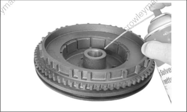
Align the flywheel keyway and install flywheel.
Coat the threads of the flywheel nut with Triple- Guard grease.
Install the washer and nut and tighten to a torque of 100 to 110 ft. lbs. (135 to 150 N·m).
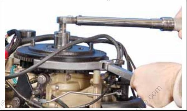
Replace recoil starter.
IMPORTANT: Check ignition timing after fly wheel removal or replacement. Refer to TIMING ADJUSTMENTS on p. 135.
TIMING ADJUSTMENTS
Timing Pointer
The timing pointer on Evinrude E-TEC 25 – 30 HP models is not adjustable.
Timing Verification
Use Evinrude Diagnostics software to synchronize the mechanical timing of the outboard with the electronic timing of the EMM.
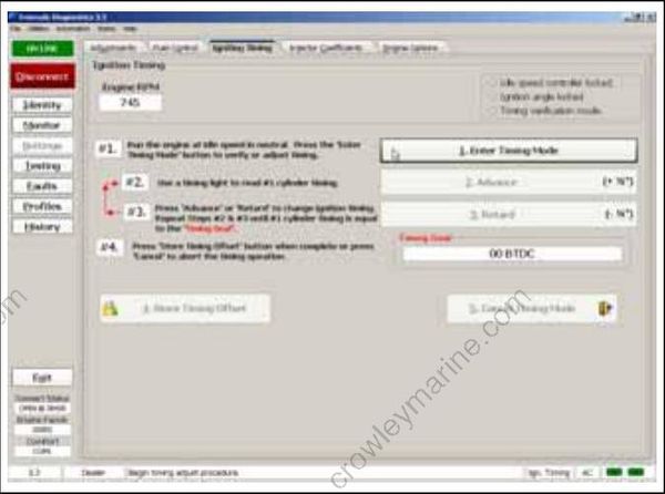
Ignition Timing Screen
Check ignition timing after any of the following procedures:
- Powerhead replacement
- Crankshaft replacement
- Flywheel removal or replacement
- CPS replacement
- EMM replacement
- EMM software replacement (reprogramming)
IMPORTANT: Make sure the timing pointer is set and the outboard reaches operating temperature before making any timing adjustments.
