

ELECTRICAL HARNESS CONNECTIONS
Inspect wiring and electrical connections. Disassemble and clean all corroded connections. Replace damaged wiring, connectors, or terminals. Repair any shorted electrical circuits. Refer to wiring diagrams and reference charts for specific wiring details.
Refer to CONNECTOR SERVICING on p. 141.
Engine Harness to Stator Connector
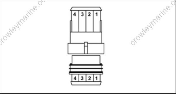
007444
| PinNo. | Description of Circuit | Wire Color |
|---|---|---|
| 1 | Stator winding (yellow) | Yellow/White |
| 2 | Stator winding (yellow) | Yellow |
| 3 | Stator winding (brown) | Brown/White |
| 4 | Stator winding (brown) | Brown |
EMM J1-A Connector
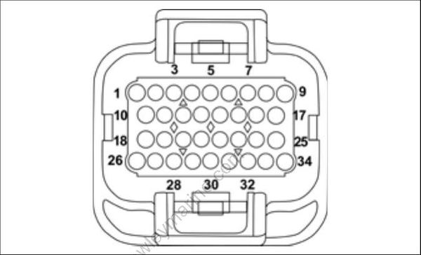
001875
| PinNo. | Description of Circuit | Wire Color |
|---|---|---|
| 1 | Ignition, cylinder 1 | Orange/Blue |
| 2 | Oil solenoid | Blue |
| 3 | Switched B+ to EMM | Purple |
| 4 | Crankshaft position sensor (CPS) | Yellow |
| 5 | Injector, cylinder 2 | Green |
| 6 | Injector, cylinder 1 | Blue |
| 7 | System Ground | Black |
| 8 | System Ground | Black |
| 9 | Stator winding, 1S | Yellow |
| 10 | CANbus, NET-H | White |
| 11 | Stop circuit | Blk/Yellow |
| 12 | Ground, CPS (digital) | White |
| 13 | Touch Troll | Red |
| 14 | Bootstrap connector (programming) | Blk/Orange |
| 15 | Ignition, cylinder 2 | Orange/Green |
| 16 | LOW OIL signal, SystemCheck | Tan/Black |
| 17 | Stator winding, 1F | Yellow/White |
| 18 | CANbus, NET-L | Blue |
| 19 | Air temperature sensor | Pink/Blue |
| 20 | Engine temperature sensor | Pink/Black |
| 21 | TPS | Green |
| 22 | Diagnostic connector | Red |
| 23 | Diagnostic connector | White |
| 24 | Tachometer | Gray |
| 25 | Stator winding, 2S | Brown |
| 26 | Fuel pump control | Brown |
| 27 | Neutral switch | Yellow/Black |
| 28 | +55V, out | White/Red |
| 29 | System ground | Black |
| 30 | +5V, out (TPS - red, Touch troll - blue) | Red |
| 31 | Low oil switch | Tan/Black |
| 32 | Stator winding, 2F | Brown/White |
| 33 | +55V, out | White/Red |
| 34 | +55V, out | White/Red |
