

DEUTSCH Connectors
IMPORTANT: Electrical Grease is recommended. Incorrect grease application can cause electrical or warning system problems.
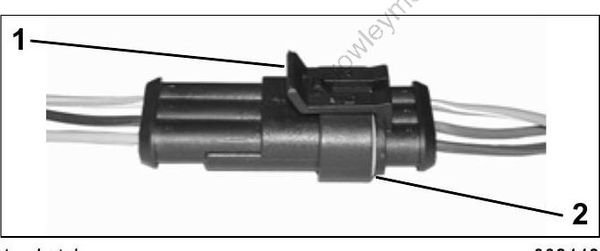
To disconnect the connector, press the latch and pull the connectors apart.
To connect the connector, confirm that the seal is in place. Clean off any old grease and dirt from connectors. Apply a light coat of Electrical Grease_ to seal. Push connectors together until latched.
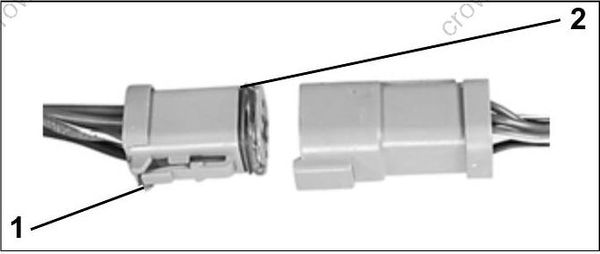
1.Latch
2.Seal
Terminal Removal
Use hook-end of Connector Service Tool, P/N 342667, to pull out wedge from receptacle, or use other end of tool to pry out wedge from plug. Use needle-nose pliers to remove wedge from 3-pin receptacle.
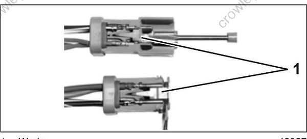
- Wedge
Release terminal latch and gently pull on wire.
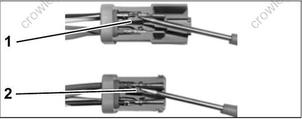
- Terminal latch (plug)
- Terminal latch (receptacle)
Terminal Installation
Push terminal through seal until it locks into place. Fill connector with Electrical Grease to 1/32 in. (0.8 mm) below ledge or end of plug.
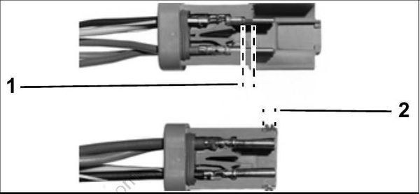
1.Ledge of plug
2.End of plug
Push wedge in until latched. Wedge in 2-pin receptacle is not symmetrical; position latch shoulders next to terminals.
Crimping Terminals
Strip insulation back 3/16 in. (5 mm). Place terminal in 18-gauge notch of Crimping Pliers, P/N 322696. Position end of wire strands in terminal past wire crimp area, and position end of insulation past insulation crimp area. Capture all wire strands in crimp; leave no loose strands. Crimp wire securely. Do not solder. Crimp insulation in 14/16-gauge notch of crimping pliers.
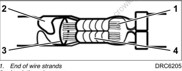
- End of wire strands
- Insulation crimp area
- End of insulation
- Wire crimp area
AMP Connectors
IMPORTANT: Always use the appropriate meter test probes and adapters when testing compo nents fitted with these terminals. Electrical grease is NOT used on AMP connectors.
SUPERSEAL†1.5
Disconnect
Lift latch. Pull connectors apart.
Connect
Confirm the seal is in place. Push connectors together until latched.
- Latch
- Seal
Terminal Removal
Use Secondary Lock Tool, P/N 777078, to release anti-backout device of connector housing. Next, use Primary Lock Tool, P/N 777077, to release locking tab of connector housing. Release locking tab and pull on wire to remove from connector housing.
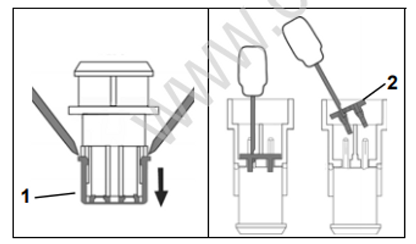
- Anti backout device, plug
- Anti backout device, receptacle
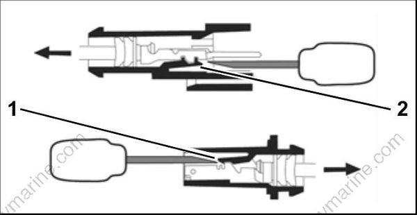
- Locking tab, plug
- Locking tab, receptacle
Terminal Installation
Align terminal with connector housing. Push connector and seal into housing until seated.
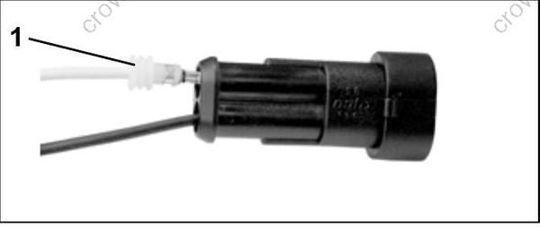
- Terminal and seal
Align anti-backout device with connector housing and terminals. Use Secondary Lock Installer,P/N 777079, to seat device in connector.
Crimping Terminals
Crimping Superseal 1.5 terminals requires AMP
Crimp Tool with dies, P/N 777281
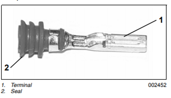
- Terminal
- Seal
SUPER SEAL†
The J1-A connector of the EMM is an AMP Super Seal_ connectors.
Disconnect
Depress BOTH latches and pull connector from plug.
Connect
Push connector into plug until latches engage.
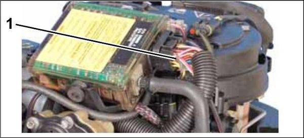
1.Latch
Terminal Removal
Open lock mechanism and remove terminal from connector housing.
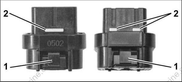
- Latch
- Lock mechanism
Terminal Installation
Push terminal through seal until it is seated in connector housing. Close lock mechanism.
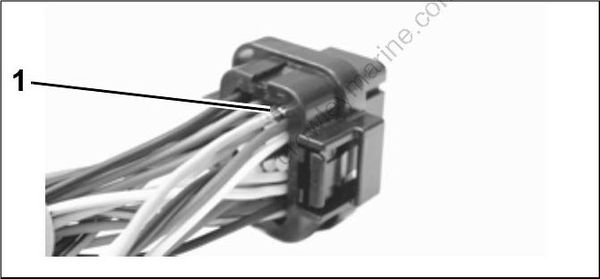
1.Terminal
Packard† Connectors
IMPORTANT: Always use the appropriate meter test probes and adapters when testing components fitted with these terminals.
Disconnect
Lift latch(s). Remove connector.
Connect
Confirm the seal is in place. Push connector onto housing until latched.
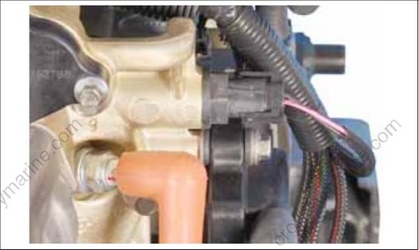
Terminal Removal
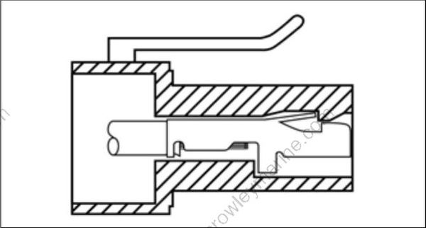
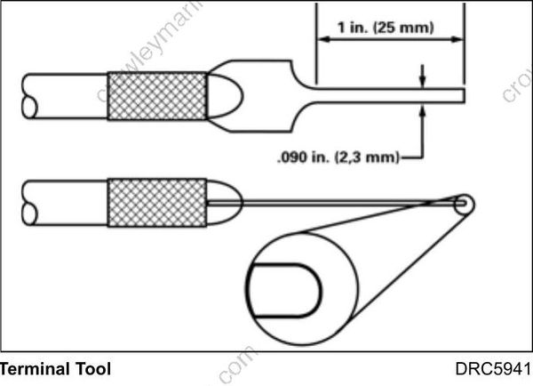
A tab on the back side of the terminal engages a shoulder in the connector housing to hold the terminal in place. The terminal is removed by pushing wire and terminal through connector housing. Insert a thin wire, such as a paper clip, into the connector above the terminal to release tab.
Terminal Installation
Terminal Installation
Install wire gasket on wires and feed wires through the correct terminal position of the connector housing. Terminal is crimped onto wire and then pulled back into connector housing until locking tab engages and terminal is seated.
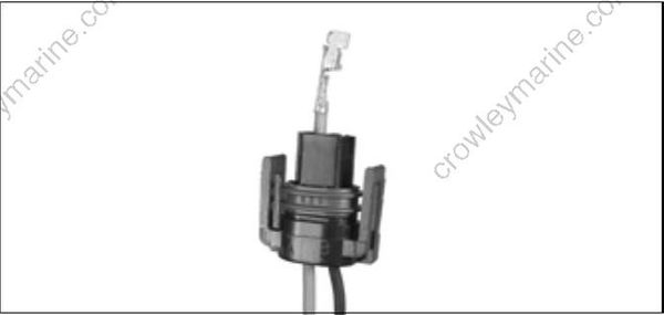
Crimping Terminals
Strip insulation back 3/16 in. (5 mm). Position end of wire strands in terminal past the wire crimp area and the end of insulation in the
insulation crimp area of the terminal.
Capture all wire strands in crimp; leave no loose strands. Crimp wire and insulation securely using crimping pliers.
