

ROUTINE INSPECTIONS
General
Check for external signs of fluid leakage. Correct causes as necessary.
Check the battery and make sure it is in good operating condition.
Reservoir Fluid
Check reservoir fluid level every three years or every 300 operating hours. System capacity is approximately 21 fl. oz. (620 ml).
Refer to Trim and Tilt on p. 81 for filling procedure.
Manual Release Valve
Check the manual release valve with a torque wrench.
IMPORTANT: Tighten valve to a torque of 45 to 55 in. lbs. (5 to 6 N•m).
Stern Brackets
Inspect the stern brackets for binding.
Tighten starboard tilt tube nut to a torque of 45 to 50 ft. lbs. (61 to 68 N•m).
TROUBLESHOOTING
If the power trim/tilt system has malfunctioned and the cause has not been determined, the Symptoms Chart on p. 339 should help locate the problem.
Keep a manual release valve and a valve body in stock for troubleshooting. Use these parts when the Service Procedures on p. 339 call for the substitution of known good parts.
If the trim/tilt does not work, and its motor neither runs nor hums, troubleshoot the problem by refer ring to TILT/TRIM RELAY TEST on p. 144.
If the outboard tilts part way up but not smoothly, or with a constant sound, there is probably air in the system due to low fluid. Fill reservoir and bleed (purge air from) the system.
To test for mechanical binding, open the manual release valve and manually tilt the motor up and down. If parts are binding, refer to MIDSECTION section.
If the outboard will not stay in shallow water drive and drops down at fast idle, the wrong manual release valve may be installed. Check for the identification groove in the face of the valve.
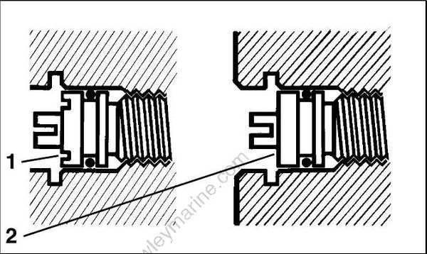
30959
- Grooves (V4 Models)
- No grooves (V6 Models)
If the outboard does not tilt as high as it should, and the tilt motor TURNS OFF at maximum tilt (does not sound like it is stalled at the maximum tilt position), adjust the tilt limit switch higher and retest. Refer to Tilt Limit Switch Adjustment on p. 68.
Symptoms Chart
If any of these symptoms describe the unit, follow the indicated Service Procedures, in the order listed, to locate and correct the problem.
| Symptom | Service Procedures |
|---|---|
| Unit will not move in either direction. | 1, 2, 3, 4, 6 |
| Unit runs slowly in one direction, normal speed in other direction. | 1, 2, 6 |
| Unit runs slowly. (if low hours)(if high hours) | 1, 2, 71, 2, 5, 7 |
| Unit leaks DOWN and/or will not hold trim position against thrust in forward. | 1, 2, 6 |
| Unit leaks both UP and DOWN – Leaks down in tilt range and/or will not hold trim position against thrust in forward or reverse. | 1, 2, 7 |
| Unit will not trim/tilt one way, but works the other way. Unit will not run DOWN, but runs UP; or it runs DOWN, but will not run UP. | 2, 3, 6 |
Service Procedures
STEP 1
Be sure the manual release valve is closed. If NOT, torque to 45 to 55 in. lbs. (5.1 to 6.2 N•m).
STEP 2
Temporarily install a known good manual release valve and retest. If symptoms remain, original valve is not the problem. Reinstall original valve. If symptoms disappear, the original valve was faulty. Remove temporary valve and replace with correct new valve.
STEP 3
Go to TILT/TRIM RELAY TEST on p. 144 to determine if problem is power supply.
STEP 4
Remove trim motor and check condition of drive coupling. If coupling is damaged, replace it.
STEP 5
Temporarily install a known good pump manifold assembly and retest. If symptoms remain, original assembly is not the problem. Reinstall original assembly.
If symptoms disappear, the original pump manifold assembly was faulty. Remove temporary assembly and replace it with correct one.
STEP 6
Install replacement pump manifold assembly and retest. If all symptoms are not corrected, recon sider the problem using the new symptoms.
STEP 7
Install O-ring kit. Look for any cylinder damage. Look for chips in fluid or impact valves. Look for other abnormal conditions. If all symptoms are not corrected, reconsider the problem using the new symptoms.
Pressure Leakdown Test
Before servicing a hydraulic unit, it should be pressure tested to determine the unit's malfunction. This test must be performed with the hydraulic unit removed from the outboard and mounted in a vise or holding fixture.
Power Trim/Tilt Service Kit, P/N 434524, allows testing of trim/tilt operation and component condition.
The “A” adapter, P/N 336658, checks operation of the UP circuit.
The “B” adapter, P/N 336659, checks operation of the DOWN circuit.
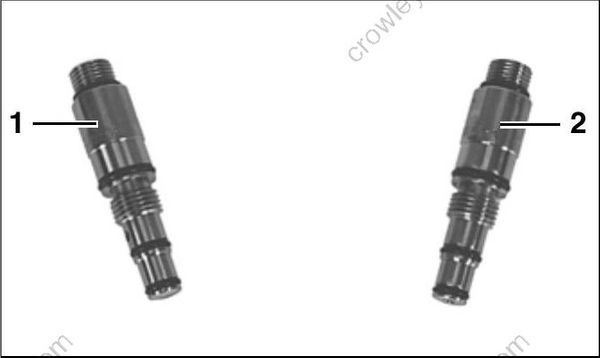
27340
This kit does not include a gauge and collar assembly. Gauge and collar assembly shipped with Power Trim/Tilt Service Kit, P/N 390010, will work. Gauge and Collar Assembly, P/N 983975, is also available.
Be sure to use a fully charged battery.
STEP 1
Screw the manual release valve in the hydraulic unit until it is seated. Place a large drain pan under the unit to catch hydraulic fluid.
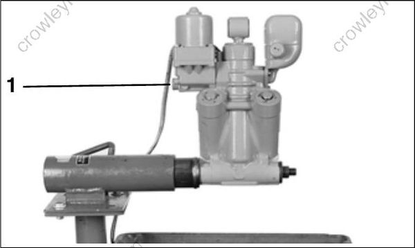
41736
- Manual release valve
Operate the unit to the full UP position, then run the unit down momentarily to reduce pressure. Loosen the reservoir cap one full turn. Loosen the manual release valve three turns. Some fluid will bypass the reservoir cap. These steps will relieve the pressure in the unit.
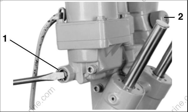
41739
1.Manual release valve
2.Reservoir cap
Remove the manual release valve retaining ring using retaining ring pliers.
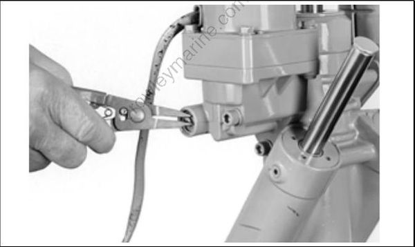
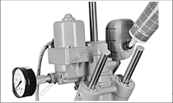
41754 Remove the manual release valve. Install pressure gauge and adapter “A” to check problems in the UP circuit.
IMPORTANT: Torque gauge and adapter lightly to 5 to 10 in. lbs. (0.6 to 1.2 N•m). Excessive torque might damage adapter or O-rings.
Cycle the unit down and up several times to purge air. With all rods fully extended, run the unit down momentarily to reduce pressure. Check fluid level again, and add fluid if necessary. Remember that all rods must be completely extended to check fluid level.
41757
Starting with the tilt cylinder fully retracted, run the unit UP.
- The gauge should show 0 to 200 psi (0 to 1379 kPa) as the tilt cylinder is extending.
- The gauge should show 1400 to 1600 psi (9653 to 11032 kPa) as the unit stalls.
- Release the switch and watch for a pressure drop. The stall pressure reading must not drop more than 200 psi (1379 kPa) after motor stops. If results vary from the above limits, there is a problem in the UP circuit. Refer to MODES OF OPERATION on p. 332 for circuit description.
STEP 2
Remove the manual release valve retaining ring using retaining ring pliers.
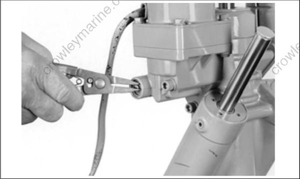
41754
Remove the manual release valve. Install pressure gauge and adapter “B” to check problems in the DOWN circuit. Cycle the unit down and up several times to purge air. With all rods fully extended, run the unit down momentarily to reduce pressure. Check fluid level again, and add fluid if necessary. Remember that all rods must be completely extended to check fluid level.
Starting with the tilt cylinder fully extended, run the unit DOWN.
- The gauge should show 0 to 200 psi (0 to 1379 kPa) as the tilt cylinder is retracting.
- The gauge should show approximately 800 psi (5516 kPa) as the unit stalls.
- Release the switch and watch for a pressure drop. The stall pressure reading must not drop more than 200 psi (1379 kPa) after motor stops. If results vary from the above limits, there is a problem in the DOWN circuit. Refer to MODES OF OPERATION on p. 332 for circuit description.
After tests are complete, run the unit up, then down momentarily. Cycle the unit down and up several times to purge air. With all rods fully extended, run the unit down momentarily to reduce pressure.
Check fluid level again and add fluid, if necessary.
