

Shift Housing Disassembly
Wear safety glasses to avoid injury
IMPORTANT: The shift housing and bearing are serviced as an assembly. If either are worn or damaged, replace the complete assembly.
Insert a suitable tool under one end of the clutch dog spring and remove it from its groove by unwrapping it from around the clutch dog. Discard the spring.
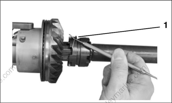
006887
- Clutch dog spring
Push the pin out of the clutch dog. Remove all parts.
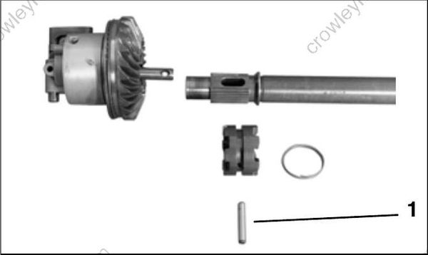
006888
Remove the gear, thrust bearing, and thrust washer from the shift housing.
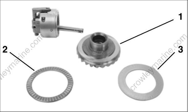
006889
- Gear
- Thrust bearing
- Thrust washer
Remove the shift lever pin from the housing. Remove shift shaft, cradle and shift lever. Move shifter detent as needed to help ease removal of parts.
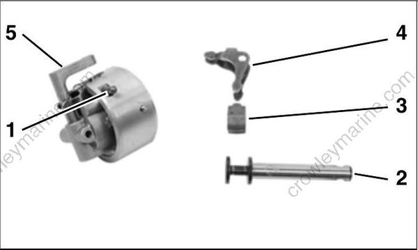
006890
- Shift lever pin
- Shift shaft
- Cradle
- Shift lever
- Shifter detent
Wear safety glasses to avoid personal injury. The detent ball and spring and come out with great force.
Wrap the housing with a shop cloth to catch ball and spring. Rotate the shifter detent 90° in either direction, then pull the detent out of the housing.
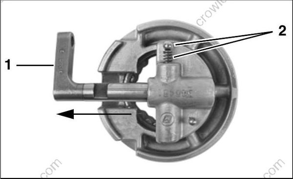
006891
- Shifter detent
- Ball and spring
Remove the detent ball and spring.
Remove needle bearings from bearing housing for cleaning and inspection.
Shift Housing Assembly
IMPORTANT: Clean and inspect all parts before beginning assembly procedures. Replace any damaged parts.
Lightly coat the detent ball and spring with Needle Bearing grease. Insert the spring in the housing, then the ball.
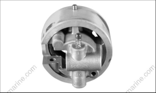
006899
Insert shifter detent at 90° angle into the housing as shown, while depressing the ball and spring with a suitable tool. Once the shifter detent is past the ball, remove the tool and position detent to engage NEUTRAL position.
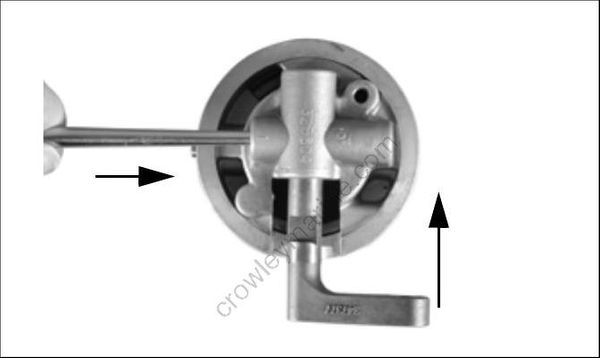
006900
Thoroughly grease 25 needle bearings with Needle Bearing grease and place in the bearing case.
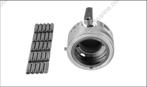
006901
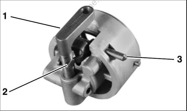
With shifter detent in NEUTRAL, install arms of shift lever into detent slots. Align the pivot holes and insert the retaining pin. Push shifter detent down.
006902
- Shifter detent
- Shift lever
- Pin, shift lever
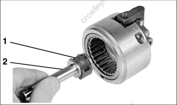
Rest the cradle on the shift shaft.
004512
- Cradle
- Shift shaft
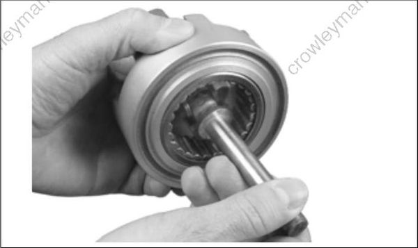
Place the shift lever arms into the recesses of the shift cradle. Pull shifter detent back up to NEUTRAL position to hold the cradle and shaft in place.
001219
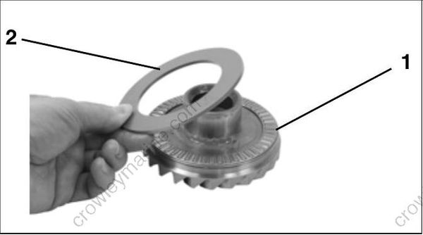
Coat thrust bearing and thrust washer with Needle Bearing grease. Place the bearing on the back of the gear. Set the washer on top of the thrust bearing. Insert the gear, bearing, and washer into the bearing housing.
IMPORTANT: Bearing and washer must be installed in the correct order.
006905
- Thrust bearing
- Thrust washer
Align holes in the clutch dog with slot in the propeller shaft. Install the clutch dog on the shaft with “PROP END” facing rear of the shaft.
IMPORTANT: The clutch dog is not symmetrical. If installed backward, it will not fully engage and will immediately damage itself and the gears.
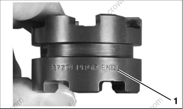
006906
- “PROP END”
Slide the propeller shaft onto the shift shaft, align the hole in the shaft with the hole in the clutch dog, install the pin and then, a new clutch dog retaining spring. Place three coils over each end of the pin, MAKING SURE NONE OF THE COILS OVERLAP OR ARE LOOSE.
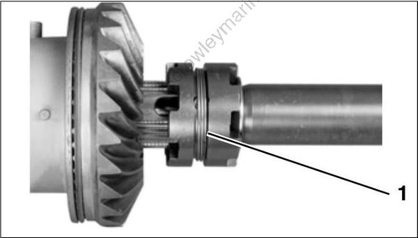
006907
- Retaining spring
Pinion Bearing Removal
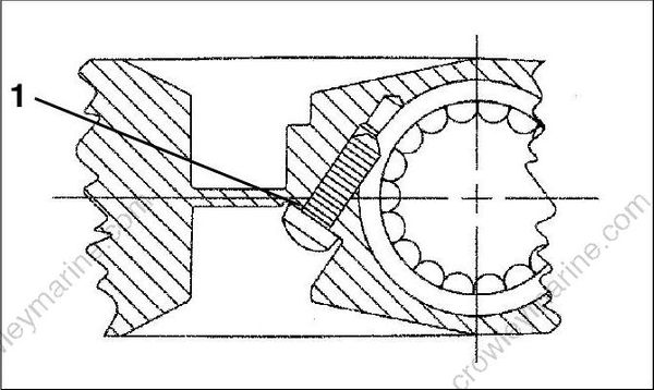
Remove pinion bearing retaining screw.
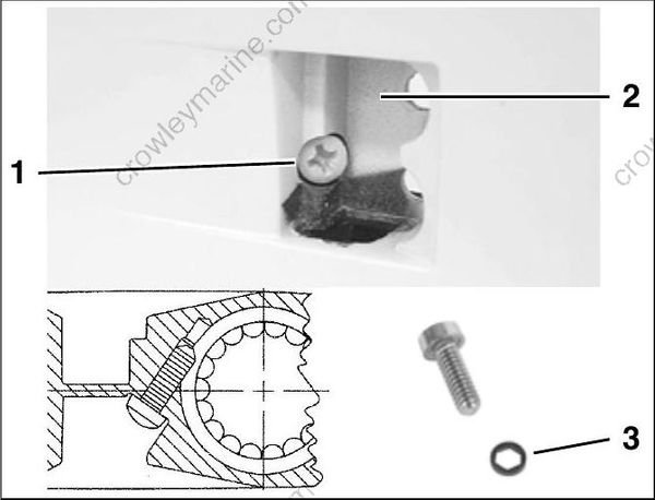
- Pinion bearing retaining screw - 006892
- Water screen pocket - DRC7416
- Seal - 006893
Assemble Pinion Bearing Remover and Installer, P/N 391257, in the gearcase as follows:
Use a 7/8 in. wrench to hold the remover in place.
Use a 3/4 in. wrench to turn flange nut clockwise.
Draw the bearing up from the housing.
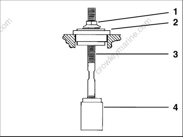
DR3419
- Flange nut, P/N 326586
- Plate, P/N 391260
- Rod, P/N 326582
- Remover, P/N 326579
Pinion Bearing Installation
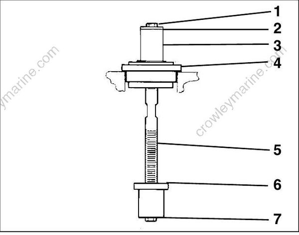
Assemble the following components of Pinion Bearing Remover and Installer, P/N 391257, as shown:
824182
- 1/4-20 X 1/2 in. Hex head screw
- 1 in. O.D. Flat washer
- Spacer; P/N 350932 “M” and “M2”
P/N 326584 “L” and “L2” - Plate and Bearing P/N 391260
- Rod P/N 326582
- Installer/Remover, P/N 350958
- 1/4-20 X 1 1/4 in. Hex head screw
IMPORTANT: Spacers are different sizes and cannot be interchanged.
Apply Needle Bearing grease to the needle bearings and insert them into the bearing case.
Place the bearing on the installer tool with the lettered side of the bearing facing the top of the gearcase. Use Needle Bearing grease to hold the bearing on the tool.
IMPORTANT: The pinion bearing is tapered so that, when installed correctly, its shape compensates for stresses in the gearcase and allows full bearing contact. Whenever a gearcase is disassembled, the pinion bearing should be checked to
ensure that it has been installed with the lettering facing up.
Insert the tool with the bearing into the gearcase. Drive the bearing into the gearcase until the washer on the tool contacts the spacer.
Remove the tool.
Position new O-ring on the pinion bearing retaining screw. Apply Gasket Sealing Compound to Oring. Apply Nut Lock to screw threads. Install the screw and tighten to a torque of 60 to 84 in. lbs. (7 to 9.5 N·m).
Driveshaft Bearing Housing Service
The driveshaft bearing is not serviceable. Replace the bearing housing assembly if the bearing is worn or damaged. Also, inspect the driveshaft bearing surface if the bearing is damaged.
Seal Removal
Remove the driveshaft bearing housing seals using Puller Bridge, P/N 432127, and Large Puller Jaws, P/N 432129. Discard the seals.
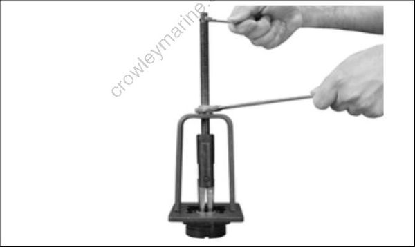
006894
Remove and discard the O-ring from the bearing housing.
Clean the bearing housing in solvent to remove sealer from the seal bore and the O-ring groove.
Seal Installation
Lightly apply Gasket Sealing Compound to a new O-ring. Install the O-ring in top groove of the bearing housing. Do not allow sealant in oil passage.
IMPORTANT: Do not install the O-ring in the bearing housing’s bottom groove. The bottom groove is an oil passage. Gearcase damage could result.
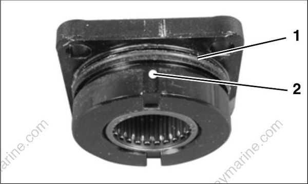
006908
- O-ring (top groove)
- Oil passage
Apply Gasket Sealing Compound to metal casings of new seals before installing.
Use Seal Installation Tool, P/N 330268 to install new seals back to back in bearing housing. Install inner seal with lip facing toward bearing housing, then the outer seal with lip facing away from bearing housing. Apply Triple-Guard grease to seal lips.
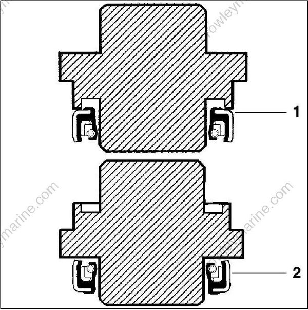
- Inner seal - DR2061
- Outer seal -
Propeller Shaft Bearing Housing Service
Rear Seal Removal
Remove seals using Puller Bridge, P/N 432127, and Small Puller Jaws, P/N 432131. Position the plate on top of the housing to support the bridge, and tighten jaws securely behind the inner seal.
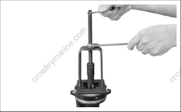
006895
Bearing Removal
IMPORTANT: Inspect bearings in place. If a bearing is removed for any reason, it must be discarded.
Remove either bearing using Puller Bridge, P/N 432127, and Large Puller Jaws, P/N 432129. Rest the puller plate on top of the housing to support the bridge, and tighten the jaws securely behind the bearing.
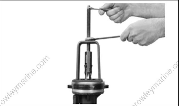
006896
Inspect the bearing housing anode. Replace anode if it is reduced to two-thirds of original size. Tighten screws to a torque of 108 to 132 in. lbs.
(12 to 15 N·m).
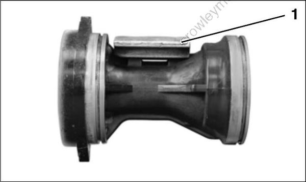
006897
- Anode
Discard the bearing housing O-rings. Clean the housing and bearings in solvent and dry thoroughly. If bearings were not replaced, rotate the needles to check for freedom of movement.
Inspect O-ring grooves. Sand off any sharp edges that might cut O-ring. Remove any nicks or burrs on front of bearing housing.
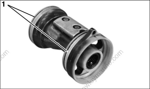
006898
- O-ring groove
Bearing Installation
Oil, then install new bearings in bearing housing.
Place the lettered end of the bearing case on the bearing installer, then press the bearing into the housing until the tool seats. When installed, the lettered end of the bearing should be visible.
STANDARD ROTATION HOUSING
Bearing Installation Tool:
• P/N 354139 – front and rear bearings
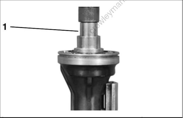
006909
Front Bearing
- Bearing installation tool
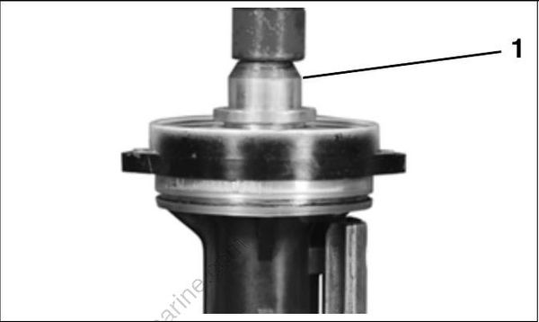
006910
Rear Bearing
- Bearing installation tool
COUNTER ROTATION HOUSING
Bearing Installation Tool:
• P/N 432401 – front bearing
• P/N 354139 – rear bearing
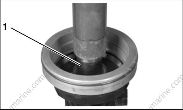
006945
Front Bearing
- Bearing installation tool
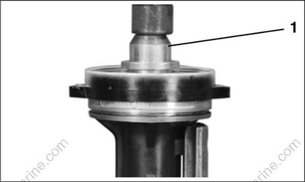
006910
Rear Bearing
- Bearing installation tool
Rear Seal Installation
Apply Gasket Sealing Compound to metal casings of the seals before installing.
Use Seal Installation Tool to install new seals back to back in bearing housing.
Seal Installation Tool:
• P/N 354056 – “L2”, “M2”
Install inner seal with lip facing toward the bearing housing, then outer seal with lip facing away from the bearing housing.
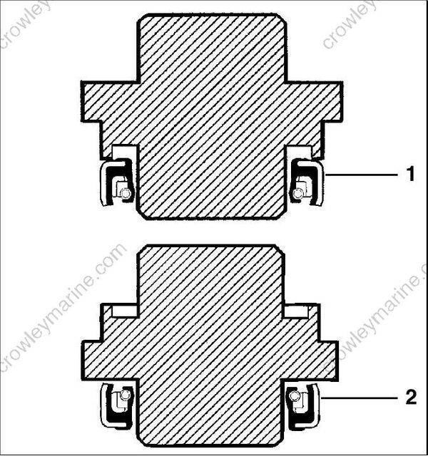
- Inner seal - DR2061
- Outer seal - DR2062
Apply Triple-Guard grease to seal lips.
