

COMPRESSION TESTING
Start and run outboard until it achieves operating temperature, then shut OFF.
Disconnect crankshaft position sensor (CPS) connector. Remove all spark plugs.
Advance throttle linkage to WOT.
Install compression tester’s hose attachment into spark plug hole (14 mm threads).
While cranking outboard with starter, note maxi mum pressure reading on gauge. Repeat procedure for each cylinder.
If engine shows a variation greater than 15 psi (100 kPa) between cylinders, check for:
- damaged cylinder head
- damaged pistons
- broken or stuck piston rings
- scored cylinder walls
Return throttle to idle position and reconnect CPS connector. Replace spark plugs. Refer to Spark Plug Indexing on p. 36.
POWERHEAD REMOVAL
Protect against hazardous fuel spray. Before starting any fuel system service, carefully relieve fuel system pressure. Refer to Relieving Fuel System Pressure on p. 130.
To prevent accidental starting while servicing, twist and remove spark plug leads.
Remove lower motor covers. Lower Cover Removal on p. 45.
Remove the recoil starter housing. Refer to RECOIL STARTER REMOVAL on p. 281.
Remove exhaust relief muffler. Refer to Exhaust Relief Muffler on p. 206.
Disconnect power trim connectors.
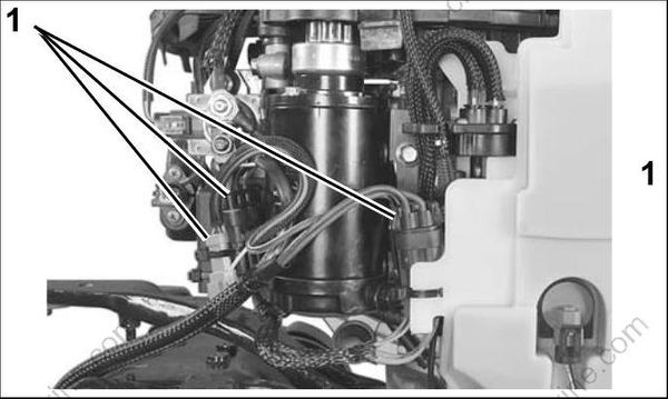
- Connectors
Remove water intake screens.
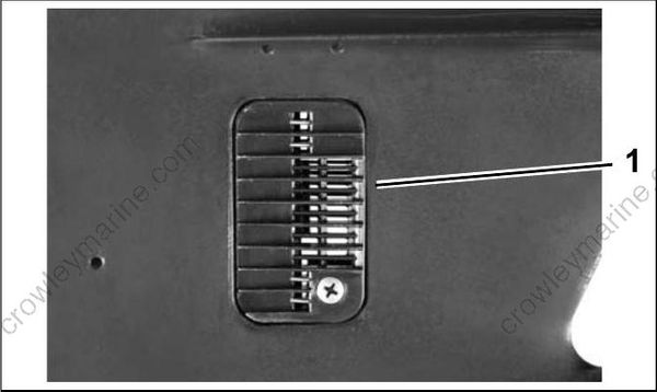
- Water intake screen
Remove the upper shift rod connector screw.
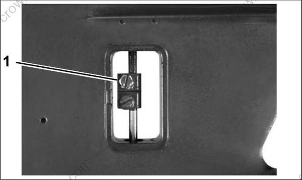
- Shift rod connector screw
Install Universal Puller Set, P/N 378103 and Lifting Eye, P/N 321537, on flywheel and seat the three screws completely.
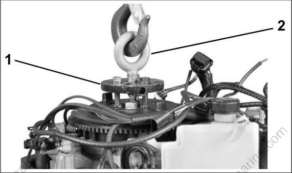
- Universal puller set
- Lifting eye
Fasten appropriate chain hook to eye of tool and support weight of powerhead with hoist.
Remove the two exhaust housing to powerhead nuts and six exhaust housing to powerhead screws.
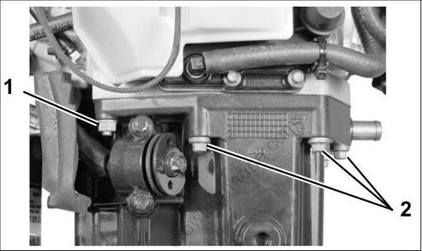
- Powerhead nuts
- Powerhead screws
Use a suitable tool to carefully separate the powerhead from exhaust housing.
IMPORTANT: Do not damage the powerhead or exhaust housing mating surfaces.
Remove clip from upper shift rod and remove shift rod.
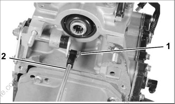
- Clip
- Shift shaft
Remove five inner exhaust housing screws and inner exhaust housing.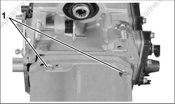
- Screws
Remove three exhaust megaphone screws and exhaust megaphone.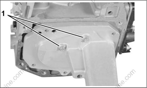
- Screws
POWERHEAD DISASSEMBLY
Systems Removal
To simplify reassembly and wiring installation, lay out the various screws and clamps in the order of their proper location.
Remove the oil tank. Refer to Oil Tank Assembly on p. 155.
Remove fuel pump assemblies, filter and fuel injectors. Refer to FUEL COMPONENT SERVICING on p. 130.
IMPORTANT: Mark injectors for cylinder location before removal. All injectors must be installed in their original location. Improper injector installation can result in powerhead failure.
Remove ignition coils.
Remove the electric starter. Refer to Starter Removal on p. 107.
Remove EMM and electrical harness assembly. Refer to EMM SERVICING on p. 66.
Remove flywheel and stator. Refer to FLYWHEEL AND STATOR SERVICING on p. 103.
Remove throttle linkage. Refer to Throttle Linkage Removal on p. 173.
Remove shift linkage. Refer to Shift Linkage Removal on p. 173.
Remove the throttle body and reed plate assemblies. Refer to Intake Manifold Service on p. 138.
Remove thermostat and pressure valve assembly. Refer to THERMOSTAT AND PRESSURE RELIEF VALVE SERVICING on p. 164.
Remove oil supply and recirculation hoses.
