

MODES OF OPERATION
(THREE PISTON SYSTEM)
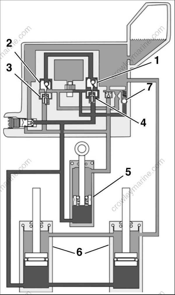
DRC3462
- Up shuttle valve
- Down shuttle valve
- Down check valve
- Up check valve
- Tilt cylinder
- Trim cylinders
- Up relief valve
The trim/tilt hydraulic assembly achieves trim and tilt movement through the following modes of operation.
Trim-OUT / Tilt-UP Mode
When the UP switch is pressed, the trim/tilt motor rotates clockwise (as viewed from pump end) and turns the pump gears.
Fluid pressure passes through the UP shuttle valve to the DOWN shuttle valve, mechanically opening the DOWN check valve.
Fluid pressure pushes the UP check valve off its seat, and fluid passes through the valve to the bottom of all cylinders, pushing the pistons UP.
Fluid is pushed from the top of the tilt cylinder by the piston and returns to the pump through the open DOWN check valve.
In the trim range, fluid is pushed from the top of the trim cylinders by the pistons and returns to the reservoir.
Only fluid from the top of the tilt cylinder is returned to the pump. Because the cylinder rod displaces some fluid, that volume is less than the volume of the bottom of the tilt cylinder. So, additional fluid is drawn into the pump from the reservoir.
Tilt-DOWN / Trim-IN Mode

DRC3463
- Down shuttle valve
- Up shuttle valve
- Up check valve
- Down check valve
- Down relief orifice
When the DOWN switch is pressed, the trim/tilt motor rotates counterclockwise (as viewed from pump end) and turns the pump gears.
Fluid pressure passes through the DOWN shuttle valve to the UP shuttle valve, which mechanically opens the UP check valve.
Fluid pressure pushes the DOWN check valve off its seat and fluid passes through the valve to the top of the tilt cylinder, moving the tilt piston DOWN.
When the swivel bracket contacts the top of the trim rods, the mechanical force of the tilt cylinder pulling the outboard down also pushes the trim pistons down. Fluid is pulled from the reservoir to the top of the trim cylinders.
Fluid from the bottom of the cylinders returns through the open UP check valve to the pump.
In the tilt range, all of the fluid from the bottom of the tilt cylinder returns through the UP check valve to the pump. Since more fluid is returning to the pump than is required to fill the top of the cylinder, the excess fluid is vented through the DOWN relief orifice to the reservoir.
In the trim range, fluid from the bottom of all the cylinders is routed to the pump, which feeds only the top of the tilt cylinder. All of the excess fluid vents through the DOWN relief orifice to the reservoir.
Impact Relief
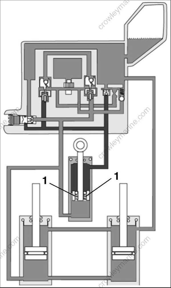
DRC3467
1.Impact relief valves
Should the gearcase hit an underwater object and the outboard suddenly tilts up, the tilt cylinder extends. The fluid above the piston is com pressed, producing high pressure.
This high pressure fluid passes through the impact relief valves in the tilt piston, dissipating much of the energy of the impact.
To return the outboard to its original position, the hydraulic unit must be operated in the DOWN direction.
Shallow Water Drive Tilt Relief

DRC3465
- Tilt relief valve
- Manual release valve
- Filter valve
If the outboard exceeds idle RPM while operating in shallow water drive mode (tilted up beyond the trim range), increased pressure beneath the tilt piston forces fluid through the tilt relief valve built into the manual release valve.
Fluid flows from below the tilt piston, through the tilt relief valve, and to the reservoir.
As the tilt piston moves down, the filter valve opens and allows fluid to flow from the reservoir to the top of the tilt cylinder.
The outboard will tilt down to the top of the trim range.
Thermal Expansion Relief
Ambient air temperature increase can cause fluid expansion within the hydraulic assembly. If the fluid expands when stored in the tilt range, the fluid under all of the pistons (and above the tilt piston) cannot expand, so its pressure increases.
If the pressure gets high enough to push the ball of the tilt relief valve off its seat, the excess pressure is vented to the reservoir.
DRC3465
- Tilt relief valve
- Manual release valve
- Filter valve
Manual Release – UP
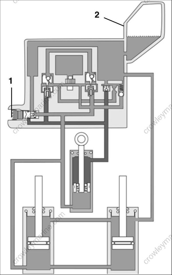
DRC3464
- Manual release valve
- Reservoir
The outboard can be positioned manually by first opening (loosening) the manual release valve.
Open the manual release valve (turn it slowly counterclockwise) with a screwdriver, about 3 1/2 turns, until it lightly contacts its retaining ring.
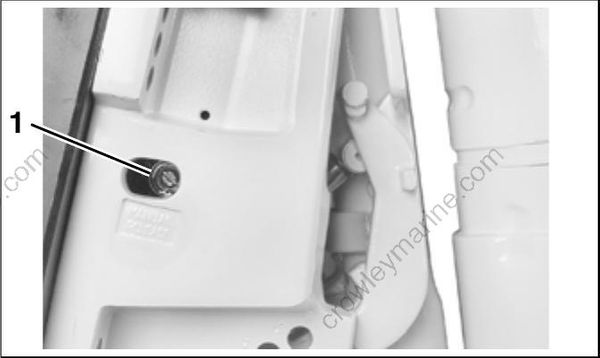
001988
1.Manual release valve
When the manual release valve is opened and the outboard is manually raised, fluid flows from the top of the tilt cylinder to the manual release valve. The fluid may pass through the manual release valve to the bottom of the tilt cylinder, or return to the reservoir. Additional fluid may be drawn from the bottom of the trim cylinders, which retract and draw additional fluid from the reservoir to the tops of the cylinders.
Trimming Outboard OUT
Pull gearcase out farther than the desired final position (up into the tilt range, if necessary).
Close the manual release valve.
Manually, push the gearcase in (or down) until it is supported by the trim system.
Open the manual release valve only enough to let the outboard trim in to desired position.
Manual Release – DOWN
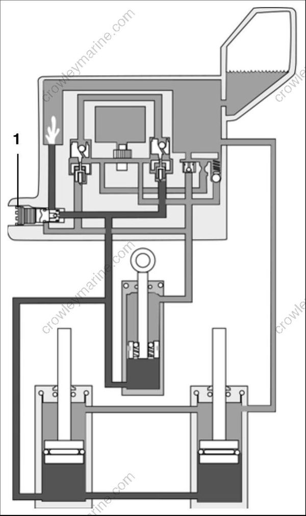
DRC3465
1.Manual release valve
When the manual release valve is opened and the outboard is manually tilted down or trimmed in, fluid flows from the bottom of the tilt cylinder (in the tilt range), or from the bottom of all of the cylinders (in the trim range), and past the manual release valve.
Fluid flows from the bottom of the tilt cylinder (in the tilt range) to the top of the tilt cylinder. The excess fluid, equal to the volume of the piston rod, is vented to the reservoir.
In the trim range, the fluid from the bottom of all three cylinders is vented to the reservoir, except for the amount required to fill the top of the tilt cylinder.
After opening the manual release valve, close it firmly. The manual release valve must be closed to enable the trim/tilt unit to function.
