

SAFETY INFORMATION
Before working on any part of the outboard, read the SAFETY section at the end of this manual.
This publication is written for qualified, factorytrained technicians who are already familiar with the use of Evinrude/Johnson Special Tools. The included information is not a substitute for work experience. It is an organized guide for reference, repair, and/or maintenance.
The following symbols and/or signal words may be used in this document:
Indicates a hazardous situation which, if not avoided, will result in death or serious injury.
Indicates a hazardous situation which, if not avoided, could result in death or serious injury
Indicates a hazardous situation which, if not avoided, could result in minor or moderate personal injury.
Indicates an instruction which, if not followed, could severely damage engine components or other property.
These safety alert signal words mean:
ATTENTION!
BECOME ALERT!
YOUR SAFETY IS INVOLVED!
IMPORTANT: Identifies information that controls correct assembly and operation of the product.
DO NOT perform any work until you have read and understood these instructions completely.
Torque wrench tightening specifications must strictly be adhered to.
Should removal of any locking fastener (lock tabs, locknuts, or patch screws) be required, always replace with a new one.
When replacement parts are required, use Evinrude/Johnson Genuine Parts or parts with equivalent characteristics, including type, strength and material. Use of substandard parts could result in injury or product malfunction.
Always wear EYE PROTECTION AND APPROPRIATE GLOVES when using power tools.
Unless otherwise specified, engine must be OFF when performing this work.
Always be aware of parts that can move, such as flywheels, propellers, etc.
Some components may be HOT. Always wait for engine to cool down before performing work.
If you use procedures or service tools that are not recommended in this manual, YOU ALONE must decide if your actions might injure people or damage the outboard.
This document may be translated into other languages. In the event of any discrepancy, the English version shall prevail.
Contact with a rotating propeller is likely to result in serious injury or death. Assure the engine and prop area is clear of people and objects before starting engine or operating boat.
Do not allow anyone near a propeller, even when the engine is off. Blades can be sharp and the propeller can continue to turn even after the engine is off. Remove propeller before servicing and when running the outboard on a flushing device.
DO NOT run the engine indoors or without adequate ventilation or permit exhaust fumes to accumulate in confined areas. Engine exhaust contains carbon monoxide which, if inhaled, can cause serious brain damage or death.
Wear safety glasses to avoid personal injury, and set compressed air to less than 25 psi (172 kPa).
The motor cover and flywheel cover are machinery guards. Use caution when conducting tests on running outboards. DO NOT wear jewelry or loose clothing. Keep hair, hands, and clothing away from rotating parts.
During service, the outboard may drop unexpectedly. Avoid personal injury; always support the outboard’s weight with a suitable hoist or the tilt support bracket during service.
To prevent accidental starting while servicing, disconnect the battery cables at the battery. Twist and remove all spark plug leads.
The electrical system presents a serious shock hazard. DO NOT handle primary or secondary ignition components while outboard is running or flywheel is turning.
Gasoline is extremely flammable and highly explosive under certain conditions. Use caution when working on any part of the fuel system.
Protect against hazardous fuel spray. Before starting any fuel system service, carefully relieve fuel system pressure.
Do not smoke, or allow open flames or sparks, or use electrical devices such as cellular phones in the vicinity of a fuel leak or while fueling.
Keep all electrical connections clean, tight, and insulated to prevent shorting or arcing and causing an explosion.
Always work in a well ventilated area.
Replace any locking fastener (locknut or patch screw) if its locking feature becomes weak.
Definite resistance to tightening must be felt when reusing a locking fastener. If replacement is indicated, use only authorized replacement or equivalent.
ABBREVIATIONS USED IN THIS MANUAL
Units of Measurement
| A | Amperes |
| amp-hr | Ampere hour |
| fl. oz. | fluid ounce |
| ft. lbs. | foot pounds |
| HP | horsepower |
| in. | inch |
| in. Hg | inches of mercury |
| in. lbs. | inch pounds |
| kPa | kilopascals |
| ml | milliliter |
| mm | millimeter |
| N·m | Newton meter |
| P/N | part number |
| psi | pounds per square inch |
| RPM | revolutions per minute |
| °C | degrees Celsius |
| °F | degrees Fahrenheit |
| ms | milliseconds |
| µs | microseconds |
| Ω | Ohms |
| V | Volts |
| VAC | Volts Alternating Current |
| VDC | Volts Direct Current |
List of Abbreviations
| ABYC | American Boat & Yacht Council |
| ATDC | after top dead center |
| AT | air temperature sensor |
| BPS | barometric pressure sensor |
| BTDC | before top dead center |
| CCA | cold cranking amps |
| CFR | Code of Federal Regulations |
| CPS | crankshaft position sensor |
| EMM | Engine Management Module |
| EPA | Environmental Protection Agency |
| ICOMIA | International Council of Marine Industry Associations |
| ID | Inside dimension |
| MCA | marine cranking amps |
| MWS | modular wiring system |
| NMEA | National Marine Electronics Assoc. |
| ROM | read only memory |
| S.A.F.E. | speed adjusting failsafe electronics |
| SAC | start assist circuit |
| SAE | Society of Automotive Engineers |
| SYNC | synchronization |
| TDC | top dead center |
| TPS | throttle position sensor |
| USCG | United States Coast Guard |
| WOT | wide open throttle |
| WTS | water temperature sensor |
EMISSION-RELATED INSTALLATION INSTRUCTIONS
Failing to follow these instructions when installing a certified engine in a vessel violates federal law (40 CFR 1068.105 (b)), subject to fines or other penalties as described in the Clean Air Act.
Maintenance, replacement, or repair of the emission control devices and systems may be performed by any marine SI (spark ignition) engine repair establishment or individual.
Manufacturer’s Responsibility
Beginning with 1999 model year outboards, manufacturers of marine outboards must determine the exhaust emission levels for each outboard horsepower family and certify these outboards with the United States of America Environmental Protection Agency (EPA). An emissions control information label, showing emission levels and outboard specifications, must be placed on each outboard at the time of manufacture.
Dealer’s Responsibility
When performing service on all 1999 and more recent Evinrude/Johnson outboards that carry an emissions control information label, adjustments must be kept within published factory specifications.
Replacement or repair of any emission related component must be executed in a manner that maintains emission levels within the prescribed certification standards.
Dealers are not to modify the outboard in any manner that would alter the horsepower or allow emission levels to exceed their predetermined factory specifications.
Exceptions include manufacturer’s prescribed changes, such as altitude adjustments, for example.
Owner’s Responsibility
The owner/operator is required to have outboard maintenance performed to maintain emission levels within prescribed certification standards.
The owner/operator is not to, and should not allow anyone to, modify the outboard in any manner that would alter the horsepower or allow emissions levels to exceed their predetermined factory specifications.
Tampering with the fuel system to change horsepower or modify emission levels beyond factory settings or specifications will void the product warranty
EPA Emission Regulations
All new 1999 and more recent Evinrude/Johnson outboards are certified to the EPA as conforming to the requirements of the regulations for the control of air pollution from new watercraft marine spark ignition outboards. This certification is contingent on certain adjustments being set to factory standards. For this reason, the factory procedure for servicing the product must be strictly followed and, whenever practical, returned to the original intent of the design. The responsibilities listed above are general and in no way a complete listing of the rules and regulations pertaining to the EPA requirements on exhaust emissions for marine products. For more detailed information on this subject, you may contact the following locations:
VIA U.S. POSTAL SERVICE:
Office of Mobile Sources
Engine Programs and Compliance Division
Engine Compliance Programs Group (6403J)
401 M St. NW
Washington, DC 20460
VIA EXPRESS or COURIER MAIL:
Office of Mobile Sources
Engine Programs and Compliance Division
Engine Compliance Programs Group (6403J)
501 3rd St. NW
Washington, DC 20001
EPA INTERNET WEB SITE:
www.epa.gov
MODEL DESIGNATION
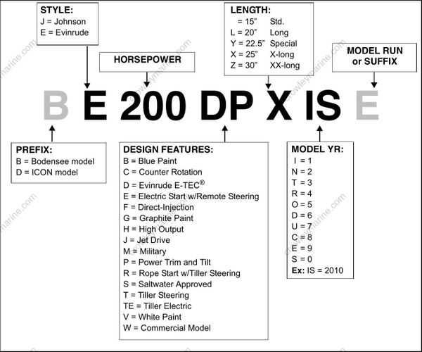
Model and serial numbers are located on the swivel bracket and on the powerhead.
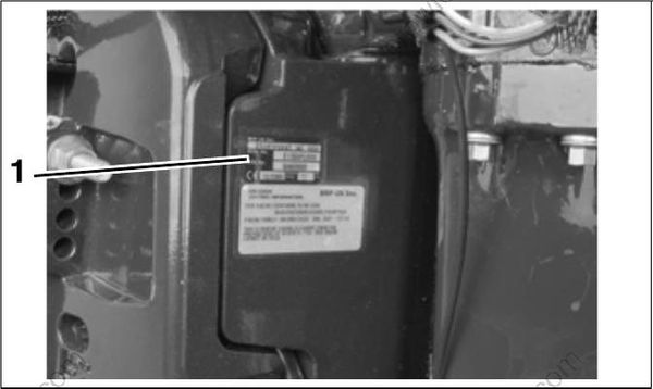
- Model and serial number
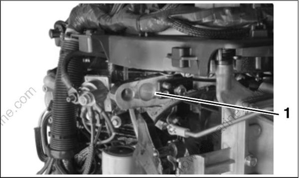
- Serial number
MODELS COVERED IN THIS MANUAL
This manual covers service information on all 105.4 cubic inch (1.7 L) and 158.2 cubic inch (2.6 L), 60° V Evinrude E-TEC models.
| Model | Displacement | Gearcase | Height | Color | Description |
|---|---|---|---|---|---|
| E115DPLISM | 1.7 L, 105.4 ci | .500 S2 | 20" | Blue | Steel Steering Arm, Standard Styling |
| E115DPLISF | 1.7 L, 105.4 ci | .500 S2 | 20" | Blue | Steel Steering Arm, Standard Styling |
| E115DSLISM | 1.7 L, 105.4 ci | .500 S2 | 20" | White | Stainless Steering Arm, Standard Styling |
| E115DSLISF | 1.7 L, 105.4 ci | .500 S2 | 20" | White | Stainless Steering Arm, Standard Styling |
| E115DBXISM | 1.7 L, 105.4 ci | .444 O | 25" | Blue | Stainless Steering Arm, Standard Styling |
| E115DBXISF | 1.7 L, 105.4 ci | .444 O | 25" | Blue | Stainless Steering Arm, Standard Styling |
| E115DPXISM | 1.7 L, 105.4 ci | .444 O | 25" | White | Stainless Steering Arm, Standard Styling |
| E115DPXISF | 1.7 L, 105.4 ci | .444 O | 25" | White | Stainless Steering Arm, Standard Styling |
| E115DCXISR | 1.7 L, 105.4 ci | .444 O CR | 25" | White | Stainless Steering Arm, Standard Styling |
| E115DCXISF | 1.7 L, 105.4 ci | .444 O CR | 25" | White | Stainless Steering Arm, Standard Styling |
| E115DHLISC | 1.7 L, 105.4 ci | .500 S2 | 20" | Blue | Steel Steering Arm, H.O. Styling |
| E115DHLISF | 1.7 L, 105.4 ci | .500 S2 | 20" | Blue | Steel Steering Arm, H.O. Styling |
| E115DHXISC | 1.7 L, 105.4 ci | .444 O | 25" | White | Stainless Steering Arm, H.O. Styling |
| E115DHXISF | 1.7 L, 105.4 ci | .444 O | 25" | White | Stainless Steering Arm, H.O. Styling |
| E115HSLISC | 1.7 L, 105.4 ci | .500 S2 | 20" | White | Stainless Steering Arm, H.O. Styling |
| E115HSLISF | 1.7 L, 105.4 ci | .500 S2 | 20" | White | Stainless Steering Arm, H.O. Styling |
| E130DPLISC | 1.7 L, 105.4 ci | .500 S2 | 20" | Blue | Steel Steering Arm, Standard Styling |
| E130DPLISF | 1.7 L, 105.4 ci | .500 S2 | 20" | Blue | Steel Steering Arm, Standard Styling |
| E130DSLISC | 1.7 L, 105.4 ci | .500 S2 | 20" | White | Stainless Steering Arm, Standard Styling |
| E130DSLISF | 1.7 L, 105.4 ci | .500 S2 | 20" | White | Stainless Steering Arm, Standard Styling |
| E130DPXISC | 1.7 L, 105.4 ci | .444 O | 25" | White | Steel Steering Arm, Standard Styling |
| E130DPXISF | 1.7 L, 105.4 ci | .444 O | 25" | White | Steel Steering Arm, Standard Styling |
| E130DCXISC | 1.7 L, 105.4 ci | 444 O CR | 25" | White | Stainless Steering Arm, Standard Styling |
| E130DCXISF | 1.7 L, 105.4 ci | 444 O CR | 25" | White | Stainless Steering Arm, Standard Styling |
| E150DPLISM | 2.6 L, 158.2 ci | .538 O | 20" | Blue | Steel Steering Arm, Standard Styling |
| E150DPLISF | 2.6 L, 158.2 ci | .538 O | 20" | Blue | Steel Steering Arm, Standard Styling |
| E150DHLISM | 2.6 L, 158.2 ci | .538 L2 | 20" | Blue | Steel Steering Arm, H.O. Styling |
| E150DHLISF | 2.6 L, 158.2 ci | .538 L2 | 20" | Blue | Steel Steering Arm, H.O. Styling |
| E150HSLISR | 2.6 L, 158.2 ci | .538 L2 | 20" | White | Stainless Steering Arm, H.O. Styling |
| E150HSLISF | 2.6 L, 158.2 ci | .538 L2 | 20" | White | Stainless Steering Arm, H.O. Styling |
| E150DSLISM | 2.6 L, 158.2 ci | .538 L2 | 20" | White | Stainless Steering Arm, Standard Styling |
| E150DSLISF | 2.6 L, 158.2 ci | .538 L2 | 20" | White | Stainless Steering Arm, Standard Styling |
| E150DBXISM | 2.6 L, 158.2 ci | .542 M2 | 25" | Blue | Stainless Steering Arm, Standard Styling |
| E150DBXISF | 2.6 L, 158.2 ci | .542 M2 | 25" | Blue | Stainless Steering Arm, Standard Styling |
| E150DPXISM | 2.6 L, 158.2 ci | .542 M2 | 25" | White | Stainless Steering Arm, Standard Styling |
| E150DPXISF | 2.6 L, 158.2 ci | .542 M2 | 25" | White | Stainless Steering Arm, Standard Styling |
| E150DCXISM | 2.6 L, 158.2 ci | .542 M2 CR | 25" | White | Stainless Steering Arm, Standard Styling |
| E150DCXISF | 2.6 L, 158.2 ci | .542 M2 CR | 25" | White | Stainless Steering Arm, Standard Styling |
| E175DPLISM | 2.6 L, 158.2 ci | .538 O | 20" | Blue | Steel Steering Arm, Standard Styling |
| E175DPLISF | 2.6 L, 158.2 ci | .538 O | 20" | Blue | Steel Steering Arm, Standard Styling |
| E175DSLISM | 2.6 L, 158.2 ci | .538 O | 20" | White | Stainless Steering Arm, Standard Styling |
| E175DSLISF | 2.6 L, 158.2 ci | .538 O | 20" | White | Stainless Steering Arm, Standard Styling |
| E175DPXISM | 2.6 L, 158.2 ci | .542 M2 | 25" | White | Stainless Steering Arm, Standard Styling |
| E175DPXISF | 2.6 L, 158.2 ci | .542 M2 | 25" | White | Stainless Steering Arm, Standard Styling |
| E175DCXISM | 2.6 L, 158.2 ci | .542 M2 CR | 25" | White | Stainless Steering Arm, Standard Styling |
| E175DCXISF | 2.6 L, 158.2 ci | .542 M2 CR | 25" | White | Stainless Steering Arm, Standard Styling |
| E200DPLISB | 2.6 L, 158.2 ci | .538 O | 20" | Blue | Steel Steering Arm, Standard Styling |
| E200DPLISF | 2.6 L, 158.2 ci | .538 O | 20" | Blue | Steel Steering Arm, Standard Styling |
| E200DSLISB | 2.6 L, 158.2 ci | .538 O | 20" | White | Stainless Steering Arm, Standard Styling |
| E200DSLISF | 2.6 L, 158.2 ci | .538 O | 20" | White | Stainless Steering Arm, Standard Styling |
| E200DPXISB | 2.6 L, 158.2 ci | .542 M2 | 25" | White | Stainless Steering Arm, Standard Styling |
| E200DPXISF | 2.6 L, 158.2 ci | .542 M2 | 25" | White | Stainless Steering Arm, Standard Styling |
| E200DCXISB | 2.6 L, 158.2 ci | .542 M2 CR | 25" | White | Stainless Steering Arm, Standard Styling |
| E200DCXISF | 2.6 L, 158.2 ci | .542 M2 CR | 25" | White | Stainless Steering Arm, Standard Styling |
SERVICE SPECIFICATIONS
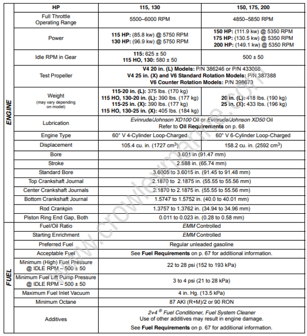

STANDARD TORQUE SPECIFICATIONS
| Size | In. Lbs. | Ft. Lbs. | N·m |
|---|---|---|---|
| No. 6 | 7–10 | 0.58–0.83 | 0.8–1.1 |
| No. 8 | 15–22 | 1.25–1.83 | 1.7–2.5 |
| No. 10 | 24–36 | 2–3 | 2.7–4.0 |
| No. 12 | 36–48 | 3–4 | 4.0–5.4 |
| 1/4 in. | 60–84 | 5–7 | 7-9.5 |
| 5/16 in. | 120–144 | 10–12 | 13.5–16.5 |
| 3/8 in. | 216–240 | 18–20 | 24.5–27 |
| 7/16 in. | 336–384 | 28–32 | 38–43.5 |
| M3 | 15–22 | 1.25–1.83 | 1.7–2.5 |
| M4 | 24–35 | 2–2.9 | 2.7–4.0 |
| M5 | 35–60 | 2.9–5 | 4.0–6.8 |
| M6 | 84–106 | 7–8.8 | 9.5–12 |
| M8 | 177–204 | 14.7–17 | 20–23 |
| M10 | 310–336 | 25.8–28 | 35–38 |
IMPORTANT: These values apply only when a specific torque for a specific fastener is not listed in the appropriate section. When tightening two or more screws on the same part, DO NOT tighten screws completely, one at a time.
Torque wrench tightening specifications must be strictly adhered to. Replace any locking fastener (locknut or patch screw) if its locking feature becomes weak. Definite resistance to turning must be felt when reusing a locking fastener.
If replacement is specified or required because the locking fastener has become weak, use only authorized Evinrude/ Johnson Genuine Parts.
PRODUCT REFERENCE AND ILLUSTRATIONS
BRP US Inc. reserves the right to make changes at any time, without notice, in specifications and models and also to discontinue models. The right is also reserved to change any specifications or parts, at any time, without incurring any obligation to equip same on models manufactured prior to date of such change. Specifications used are based on the latest product information available at the time of publication.
The continuing accuracy of this manual cannot be guaranteed.
All photographs and illustrations used in this manual may not depict actual models or equipment, but are intended as representative views for reference only.
Certain features or systems discussed in this manual might not be found on all models in all marketing areas.
All service technicians must be familiar with nautical orientation. This manual often identifies parts and procedures using these terms.
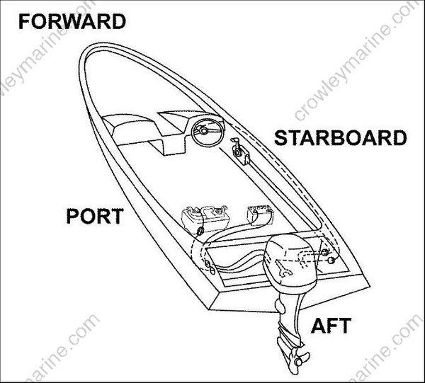
Nautical Orientation
