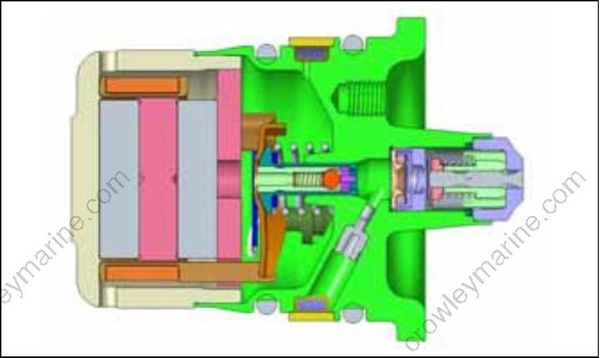
COMPONENTS
The fuel system includes the following components:
Fuel Lift Pump
Fuel Filter
Vapor Separator
Fuel Circulation Pump
Fuel Supply Manifolds
Fuel Injectors
Fuel Return Manifolds
Fuel Lift Pump
The fuel lift pump is a mechanical, pressure-pulse pump. The diaphragm of the pump is driven by two pulse hoses that connect to the cylinder/crankcase assembly.
Fuel lift pump pulse hose locations:
V4 models: Cylinders 2 and 4
60° V6 models: Cylinders 4 and 6
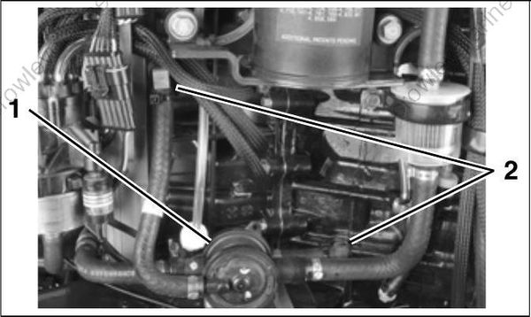
- Fuel lift pump
- Pulse hose fittings
Vacuum from the fuel lift pump pulls fuel from the fuel tank. Once fuel reaches the pump, internal pump pressure forces the fuel from the pump through the fuel filter and into the vapor separator.
Fuel Filter
The fuel filter protects the vapor separator and the high-pressure components of the fuel system from contaminants. Refer to INSPECTION AND MAINTENANCE SCHEDULE on p. 84 for service frequency
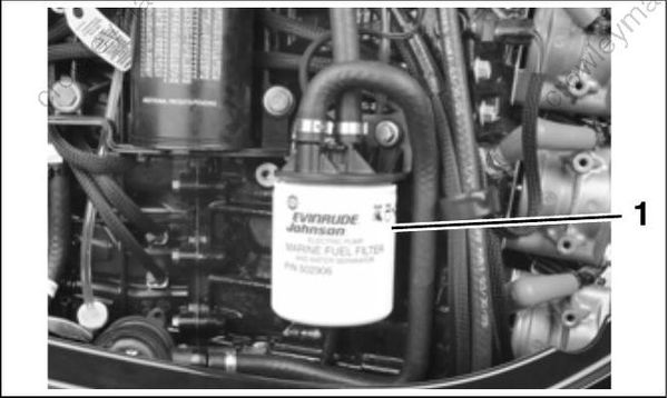
- Water-separating fuel filter
Vapor Separator
The vapor separator:
Serves as a water-cooled fuel reservoir to accumulate incoming fuel from the fuel lift pump and from the fuel return manifold
Contains a float controlling the venting of fuel vapors
Contains a fuel pressure regulator for the high pressure fuel system.
The vapor separator is serviced as an assembly and includes the fuel circulation pump.
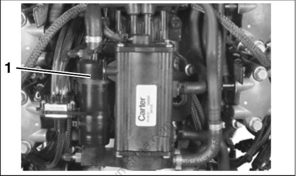
Vapor Separator Assembly
- Circulation pump
Fuel Reservoir
The vapor separator accumulates fuel in an internal fuel reservoir and supplies fuel to the electric circulation pump. It is water-cooled to enhance vapor separating capabilities.
Cooling
Water is used to cool the fuel as it flows through the vapor separator. The cooling passage of the separator self-drains when the outboard is stored vertically. Refer to HOSE ROUTING AND WATER FLOW DIAGRAMS on p. 228.
Venting
The fuel vapor vent regulates fuel vapor pressure in the reservoir.
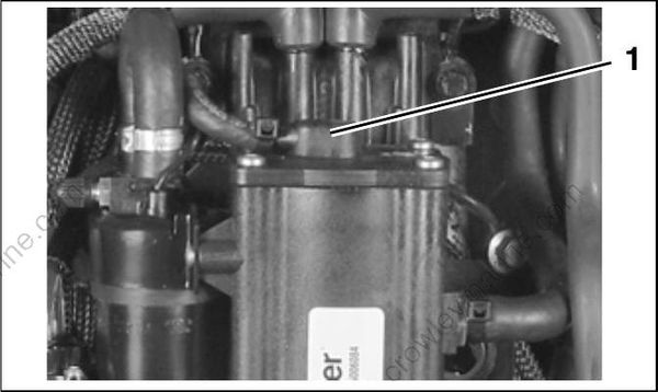
- Vent
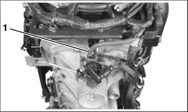
- Vent hose connection to intake
The vapor separator vent is opened and closed by a float valve. The float valve moves relative to the fuel level in the fuel chamber. Hot fuel causes an increase in vapor pressure. This results in a lower fuel level in the vapor separator. The float valve drops and the vent opens. This allows fuel vapor to flow to the intake manifold through the vent hose.
As the vapor pressure in the vapor separator decreases, the fuel level begins to increase. An increase in the fuel level raises the float valve and the vent closes.
Pressure Regulator
The fuel pressure regulator helps maintain consistent fuel pressure in the fuel system.
Fuel returning from the injectors enters the fuel chamber of the vapor separator through a pressure regulator. The pressure regulator maintains approximately 20 to 30 psi (138 to 207 kPa) of fuel pressure in the high pressure side of the fuel sys tem.
Fuel Circulation Pump
The fuel circulation pump is an electric high pressure fuel pump.
Fuel Supply
The pump is mounted to the vapor separator and draws fuel from the fuel chamber. It pumps pressurized fuel through a fuel supply manifold connected to the fuel injectors.
Electrical Circuit
The circulation pump is controlled by the EMM and operates on the 12 V circuit. The circulation pump is activated momentarily when the EMM powers up. The EMM controls pump operation by rapidly connecting and disconnecting the pump’s internal coil to ground.
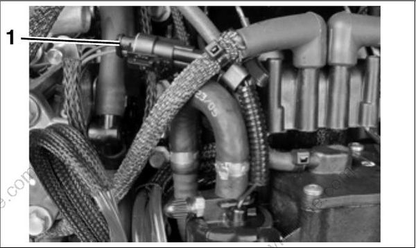
- Fuel pump electrical connector
Fuel Manifolds
The fuel supply and return manifolds route fuel through the high pressure side of the fuel system.
Fuel Supply Manifold
The fuel supply manifold supplies pressurized fuel to the inlet port of each fuel injector.
Fuel Return Manifold
The fuel return manifold provides a route for fuel passing through the fuel injectors to flow back to the fuel chamber of the vapor separator.
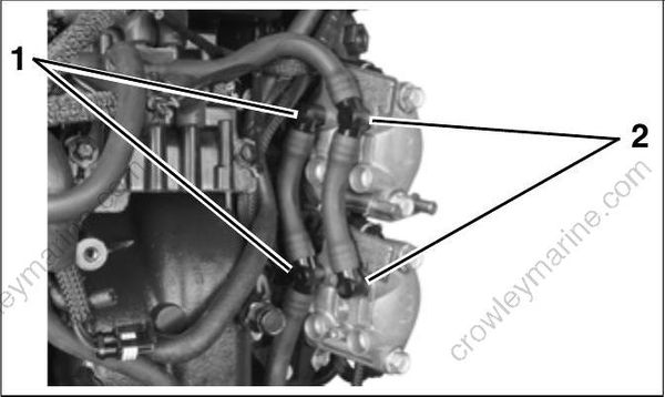
- Fuel supply
- Fuel return
Fuel Injectors
Fuel injectors are fuel metering, electric solenoids (55 V) bolted directly to the cylinder head. The EMM controls the activation of each injector by rapidly connecting and disconnecting the injector’s internal coil to ground.
Fuel Flow Compensation
The flow rate of each injector is measured as part of the manufacturing process. This information is recorded and assigned to the injector by serial number.
The EMM is programmed to compensate for variations in fuel flow. Each injector and its location on the outboard is identified by the EMM. DO NOT install an injector without updating the compensation software.
Each service injector includes its fuel flow information on a 3.5 in. floppy disk. This software allows the EMM to be reprogrammed for this injector’s unique fuel flow characteristics.
Fuel injectors MUST NOT be moved from one cylinder to another. EMM programming is associated with the cylinder location of each injector. Installing an injector on the wrong cylinder can result in powerhead failure.
Injector Fuel Supply
Fuel is supplied to the injectors by the fuel circulation pump and the fuel supply manifold.
Each injector has internal fuel passages. These passages are designed to:
Provide fuel to the injector's injection chamber
Route fuel through the injector housing to cool the injector coil and armature