

IGNITION SYSTEM CIRCUIT DIAGRAM – V4

1.Key switch (stop circuit)
2.Fuse
3.Stator
4.EMM
5.Crankshaft position sensor
6.Capacitor
7.Ignition coil
8.Main harness ground
9.+12 V from battery
IGNITION SYSTEM CIRCUIT DIAGRAM – V6
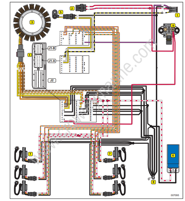
1.Key switch (stop circuit)
2.Fuse
3.Stator
4.EMM
5.Crankshaft position sensor
6.Capacitor
7.Ignition coil
8.Main harness ground
9.+12 V from battery
