

Water Intake Screens
Install water intake screens. Tighten screws to a torque of 60 to 84 in. lbs. (7 to 9.5 N·m).
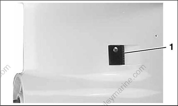
- Water intake screen 001991
Shift Housing, Gear, and Propeller Shaft Installation
Push shifter detent into farthest downward position. Tip the rear of the gearcase slightly downward to assist in the installation of the shaft assembly.
Be sure the thrust bearing and the thrust washer are in the proper position. Insert the shaft assembly fully into the gearcase while aligning shift housing pin with hole in forward end of gearcase housing.
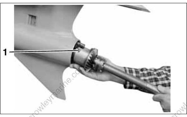
- Pin 005427
Shift Rod Cover
Lubricate a new shift rod cover O-ring with Triple- Guard grease. Install the O-ring into the shift rod cover.
IMPORTANT: Make sure O-ring is fully seated in grove.
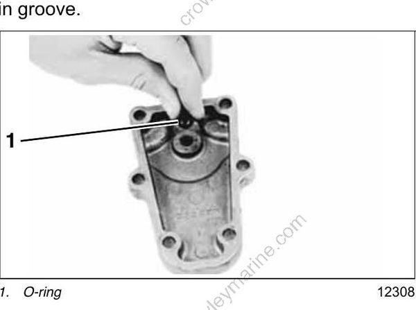
- O-ring 12308
Install pitot tube screw and seal in housing. (“S”, “O” and “M” Type)
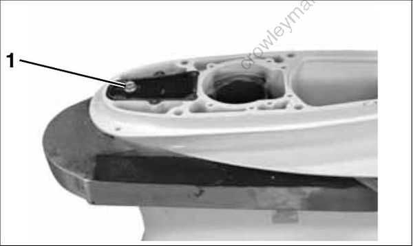
- Screw and seal 006841
Place the shift rod grommet on the shift rod. Install shift rod spacer under grommet on 25 in. models.
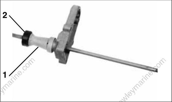
- Grommet COA3568
- Shift rod spacer (25” models)
Apply Triple-Guard grease to the threaded end of the shift rod and insert it through the cover. Turn the shift rod while pushing it through the cover to avoid damaging the O-ring.
“S2”, “O”, “L”, “L2” AND “M” TYPE GEARCASES
Apply Gasket Sealing Compound to both sides of a new shift rod cover gasket. Place the gasket on the gearcase
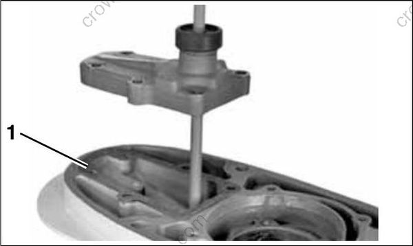
- Cover gasket COA3141
“M2” TYPE GEARCASES
Apply Adhesive 847 to seal groove of shift rod cover. Place a new shift rod cover seal in groove.
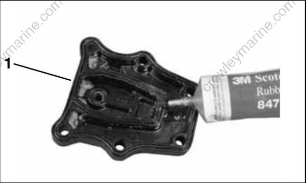
- Cover seal 006842
ALL GEARCASES
Thread the shift rod into the shifter detent about four turns.
Move shift rod from side to side while pushing on the propeller shaft to ensure proper alignment of the bearing housing locator pin into the locator pin hole in the gearcase.
Apply Gasket Sealing Compound to the threads of the shift rod cover screws. Tighten the screws to a torque of 60 to 84 in. lbs. (7 to 9.5 N·m).
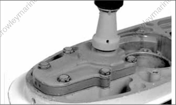
COA3569
Refer to SHIFT ROD ADJUSTMENT on p. 306.
Pinion Gear and Driveshaft Installation – “S2” Type
Refer to DRIVESHAFT SHIMMING on p. 325.
Position the driveshaft thrust bearing, thrust washer, and correct shim(s) on driveshaft as
shown.
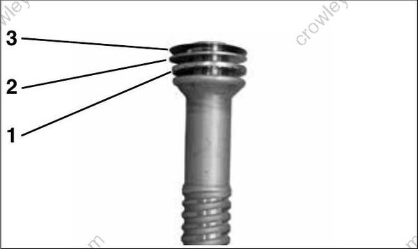
- Thrust bearing 005418
- Thrust washer
- Shim(s)
Push down on shift rod to move the clutch dog to reverse position. Pull propeller shaft aft to disengage from forward gear and shift housing. Allow shaft to drop against lower gearcase housing. This will allow the installation of the pinion gear.
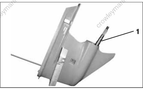
IMPORTANT: Forward gear and thrust bearing and washer can become misaligned. Make sure forward thrust washer and thrust bearing and for ward gear are properly aligned with shift housing before continuing gearcase assembly.
Install pinion gear in gearcase housing
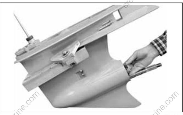
005420
Install driveshaft with thrust bearing, thrust washer, and correct shim(s) in gearcase housing. Position pinion on lower driveshaft.

005410
Position pinion screw in lower driveshaft and thread into pinion.
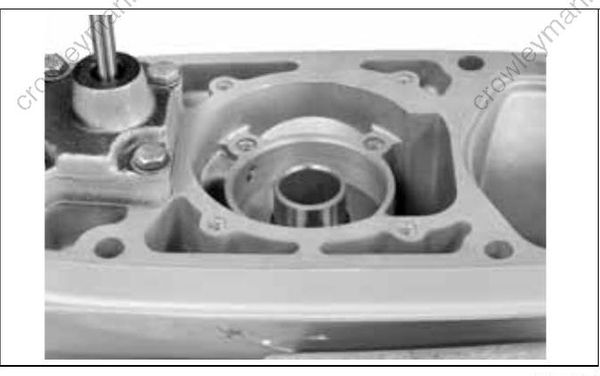
005421
IMPORTANT: Temporarily install bearing housing for support during pinion tightening procedure.
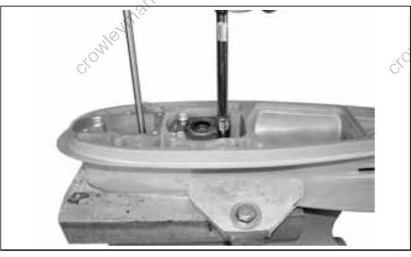
005426
Insert Lower Driveshaft Wrench, P/N 352877, through Lower Driveshaft Spline Tool and lower driveshaft. Seat hex tip of wrench in head of pinion screw
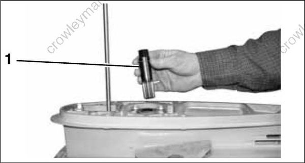
- Lower Driveshaft Spline Tool 005407
Insert Lower Driveshaft Wrench, P/N 352877, through Lower Driveshaft Spline Tool and lower driveshaft. Seat hex tip of wrench in head of pin ion screw.
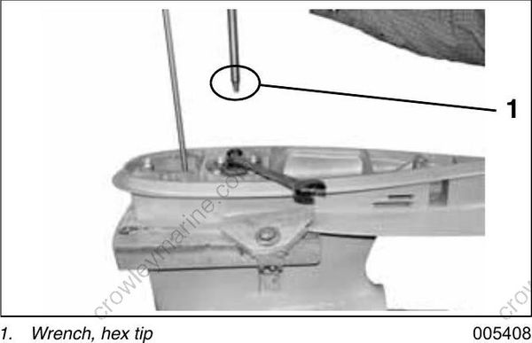
IMPORTANT: Make sure Lower Driveshaft Wrench is fully seated in head of pinion screw.
Use a long 3/4 in. combination wrench to hold Driveshaft Spline Tool and a 1/2” drive torque wrench to turn the Lower Driveshaft Wrench in a clockwise direction. Torque pinion screw to 37 to 41 ft. lbs. (50 to 56 N·m).
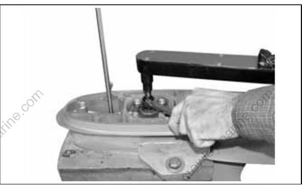
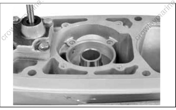
Temporarily remove the four driveshaft bearing housing screws and bearing housing.
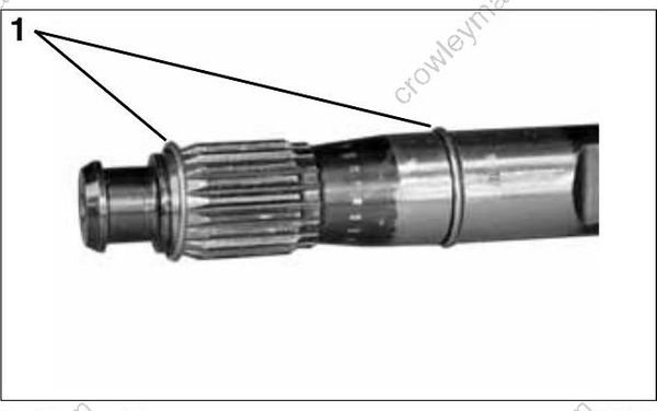
To install upper driveshaft into lower driveshaft, position new retainers (circlip type) on upper driveshaft as shown.
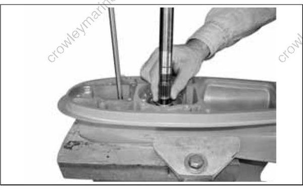
Hold lower retainer and align upper driveshaft with lower driveshaft. Force upper driveshaft down until seated. Driveshaft should lock in place.
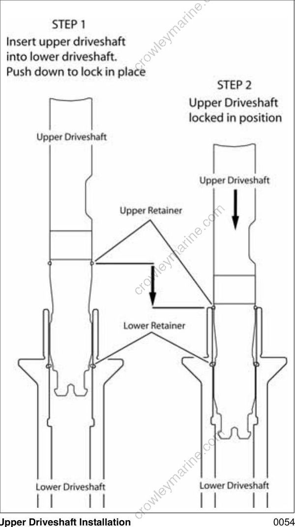
Upper Driveshaft Installation 0054
Install new seals in driveshaft bearing housing. Refer to Driveshaft Bearing Housing Service** on p. 321. Using Driveshaft Seal Protector, P/N 318674, slide the driveshaft bearing housing onto the driveshaft.
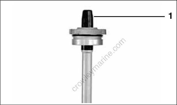
- Seal protector COA3130
COA3130 Install washers on the driveshaft bearing housing screws. Apply Gasket Sealing Compound to the threads of the screws. Install screws and tighten to a torque of 120 to 144 in. lbs. (13.5 to 16.5 N·m).
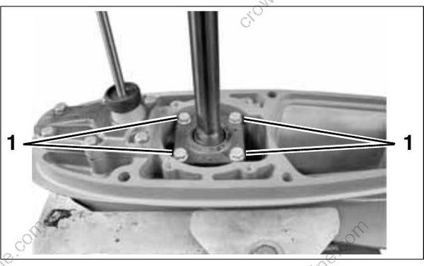
- Driveshaft bearing housing screws 005425
Pinion Gear and Driveshaft Installation – “O”, “L”’ “L2”, “M” and “M2” Type
Refer to DRIVESHAFT SHIMMING on p. 325.
Install new seals in driveshaft bearing housing. Refer to Driveshaft Bearing Housing Service on p. 321.
Place the driveshaft thrust bearing, thrust washer, and correct shim(s) on the driveshaft as shown.
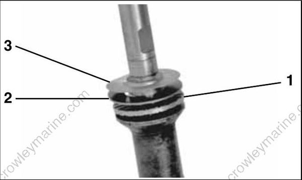
- Thrust bearing COA3168
- Thrust washer
- Shim(s)
Using Driveshaft Seal Protector, P/N 318674, slide the driveshaft bearing housing onto the driveshaft and into position in the gearcase.
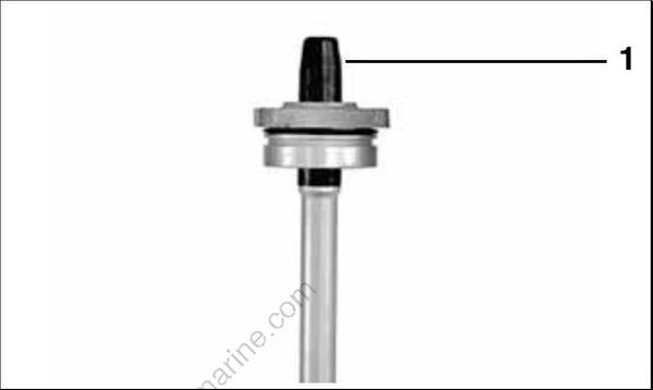
- Seal protector COA3130
Adjust shift rod to move clutch dog as far forward as possible. Be sure excess grease is removed from the pinion bearing.
Washer must be snapped into recess of pinion gear.
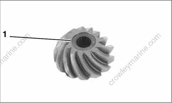
- Washer DSC02293
IMPORTANT: The inside taper of the pinion gear and the driveshaft taper MUST be completely free of grease. Clean the tapers with Cleaning Solvent. Use a shop towel free of grease and lint.
Lightly coat the threads of a new pinion nut with outboard lubricant. Use Pinion Nut Starting Tool, P/N 342216, to install nut on the driveshaft. Turn the driveshaft by hand to thread the nut on to shaft.
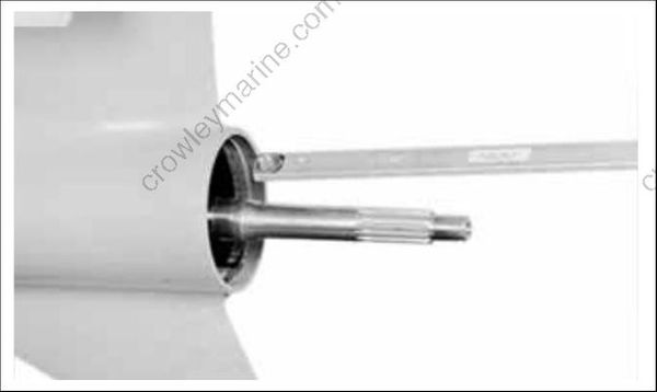
42230
Apply Gasket Sealing Compound to the threads of the driveshaft bearing housing screws. Tighten screws in stages to a torque of 120 to 144 in. lbs. (13.5 to 16.5 N·m)
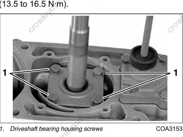
- Driveshaft bearing housing screws COA3153
Use Driveshaft Holding Socket, P/N 311875, Pinion Nut Holder, P/N 334455, and Wrench Retainer, P/N 341438, to tighten the pinion nut to a torque of 100 to 110 ft. lbs. (136 to 149 N·m). Pad handle of holder to prevent damage to gearcase.
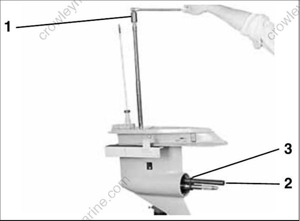
- Holding socket 42229
- Pinion holder
- Retainer
Propeller Shaft Bearing Housing and Gear Installation – “S2”, “O”, “L” and “M” Type
The propeller shaft bearing housing on these models SLIDES in or out of gearcase housing.
Oil and install thrust bearing and thrust washer on hub of reverse gear. Slide the gear assembly onto the propeller shaft until it engages the pinion gear.
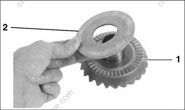
- Thrust bearing DSC02295
- Thrust washer
Lightly apply Gasket Sealing Compound to a new bearing housing O-ring. Install O-ring in groove in the housing.
Install housing into gearcase. Align screw holes with retainer slots in gearcase.
Housing must be completely seated to install retainer tabs.
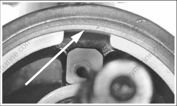
Retainer Tab Slot 50106a
Install two retainers, washers and screws. Apply Ultra Lock to threads and tighten screws to a torque of 18 to 20 ft. lbs. (24 to 27 N·m).
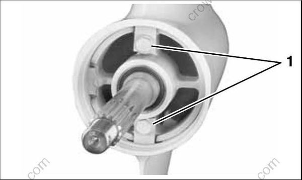
- Retainer tab screws 001989
Loosen retainer screws 1/4 turn.
Install wedge, screw, and washer. Apply Ultra Lock to threads and tighten screw to a torque of 15 to 20 in. lbs. (1.7 to 2.3 N·m).
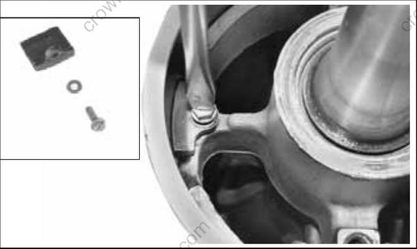
DSM02291
DSC02361
Re-tighten two retainer screws to 18 to 20 ft. lbs. (24 to 27 N·m).
Confirm that torque on the wedge screw is 15 to 20 in. lbs. (1.7 to 2.3 N·m).
Propeller Shaft Bearing Housing and Gear Installation – “L2” Type
IMPORTANT: The propeller shaft bearing housing on the “L2” type gearcases is PRESSED into the gearcase housing.
Oil and install thrust bearing and thrust washer on hub of reverse gear. Slide the gear assembly onto the propeller shaft until it engages the pinion gear.
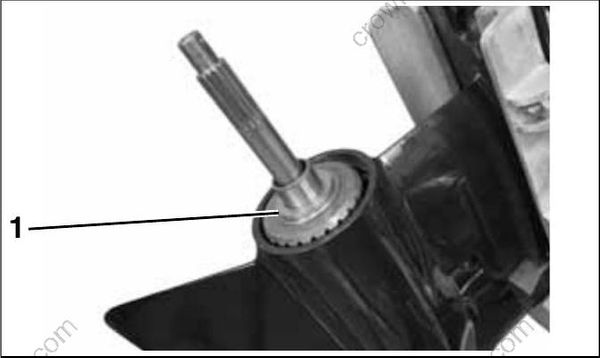
- Thrust bearing and thrust washer 006843
Lightly apply Triple Guard Grease_ to a new bearing housing O-ring. Install O-ring in groove in the housing. Grease the machined side surfaces of bearing housing.
Install housing into gearcase. Align screw holes with retainer slots in gearcase.
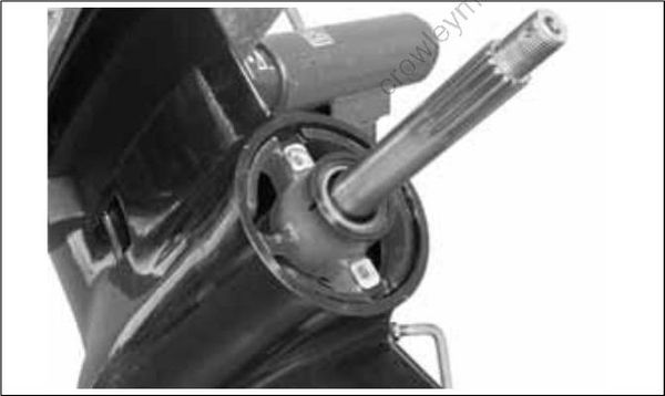
006836
Use Installer Handle, P/N 345822, Propeller Shaft Bearing Housing Installer, P/N 354058, Gearcase Fixture, P/N 354059 and an appropriate floor press (10 ton or greater) to install housing into
gearcase. Align and level gearcase assembly in fixture as shown. Secure fixture to floor press.
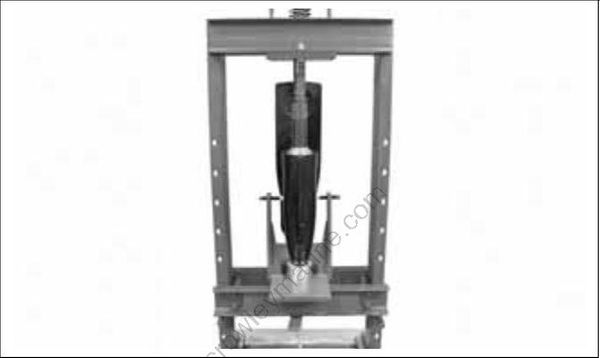
006844
Housing must be completely seated in gearcase to install retainer tabs. Depth to retainer tab sur face on bearing housing is approximately 1 in. (25.4 mm).
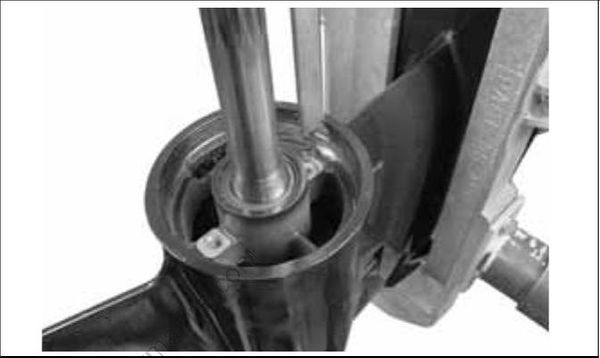
006845
Install two retainers, washers and screws. Apply Ultra Lock to threads and tighten screws to a torque of 18 to 20 ft. lbs. (24 to 27 N·m).
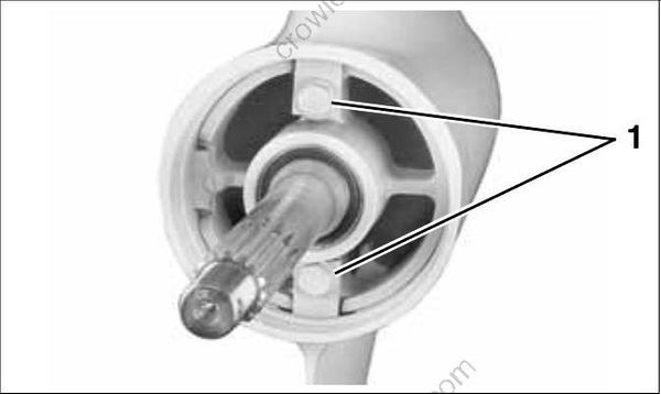
- Retainer tab screws 001989
IMPORTANT: The propeller shaft bearing housing on the “M2” type gearcases is PRESSED into the gearcase housing.
Oil and install thrust bearing and thrust washer on hub of reverse gear. Slide the gear assembly onto the propeller shaft until it engages the pinion gear.
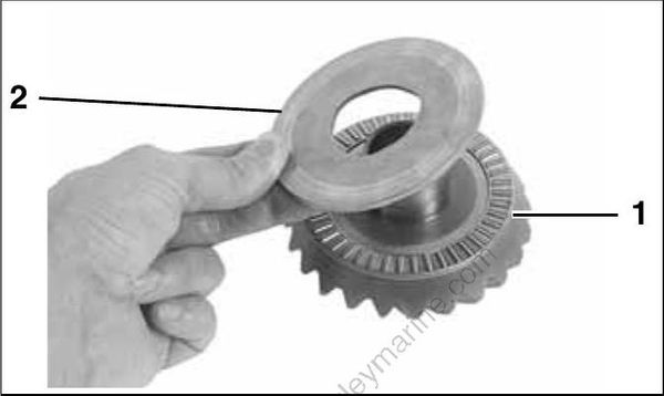
- Thrust bearing DSC02295
- Thrust washer
Lightly apply Triple Guard Grease to new bearing housing O-rings. Install O-rings in grooves in the housing. Grease the machined side surfaces of bearing housing.
Place bearing housing in gearcase.
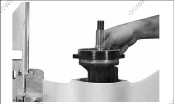
006846
Align retaining holes in bearing housing with screw holes in gearcase. Thread Alignment Pins, P/N 354140, into gearcase.
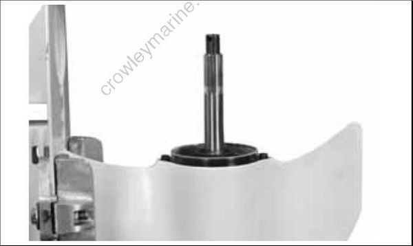
006847
Use Installer Handle, P/N 345822, Propeller Shaft Bearing Housing Installer, P/N 354057, Gearcase Fixture, P/N 354059 and an appropriate floor press (10 ton or greater) to install housing into gearcase. Align and level gearcase assembly in fixture as shown. Secure fixture to floor press.
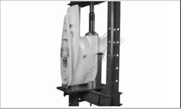
“M2” Type Gearcase 006848
Housing must be completely seated in gearcase to install retainer screws. Bearing housing is approximately level with gearcase.
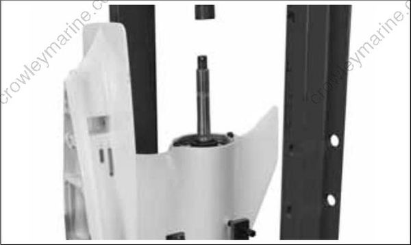
006849
Apply Ultra Lock to threads and install two retaining screws. Tighten screws to a torque of 18 to 20 ft. lbs. (24 to 27 N·m).
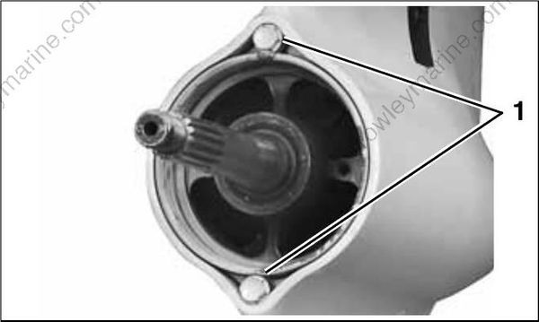
- Retainer screws 006835
Final Assembly and Adjustment
To complete gearcase assembly, refer to:
• GEARCASE LEAK TEST on p. 300
• WATER PUMP SERVICE on p. 304
• SHIFT ROD ADJUSTMENT on p. 306
• GEARCASE REMOVAL AND INSTALLATION on p. 301
• Gearcase Lubricant on p. 87
• Propeller Hardware Installation on p. 67
• Trim Tab Adjustment on p. 70
During break-in period of a reassembled gearcase, change the gearcase lubricant between 10
to 20 hours of operation.
