

EXPLODED DIAGRAM
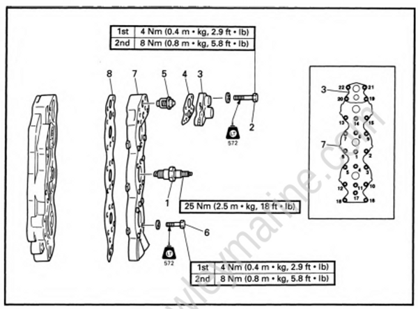
REMOVAL AND INSTALLATION CHART
| Step | Procedure/Part name | Q'ty | Service points |
|---|---|---|---|
| THERMOSTAT AND CYLINDER HEAD COVER REMOVAL | Follow the left "Step" for removal. | ||
| 1 | Spark plug | 6 | |
| 2 | Bolt (with washer) | 8 | NOTE: Tighten the bolts in sequence and in two steps of torque. |
| 3 | Thermostat cover | 2 | |
| 4 | Thermostat cover gasket | 2 | |
| 5 | Thermostat | 2 | |
| 6 | Bolt (with washer) | 36 | NOTE: Tighten the bolts in sequence and in two steps of torque. |
| 7 | |||
| 8 | Cylinder head cover | 2 | |
| Cylinder head cover gasket | 2 | ||
| Reverse the removal steps for installation. |
Thermostat inspection
- Inspect:
- Thermostat
Stick/Damage -> Replace.
- Measure:
- Valve opening temperature
- Valve lift (a)
Out of specification -> Replace.
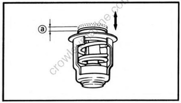
| Water temperature | Valve lift |
|---|---|
| Below 48 ~ 52 °C (118 ~ 126 °F) | 0 mm (0 in) |
| Above 60 °C (140 °F) | Min.3 mm (0.12 in) |
Measuring steps:
- Suspend thermostat in a vessel.
- Place reliable thermometer in a water.
- Heat water slowly.
- Observe thermometer, while stirring water continually.
