

EXPLODED DIAGRAM
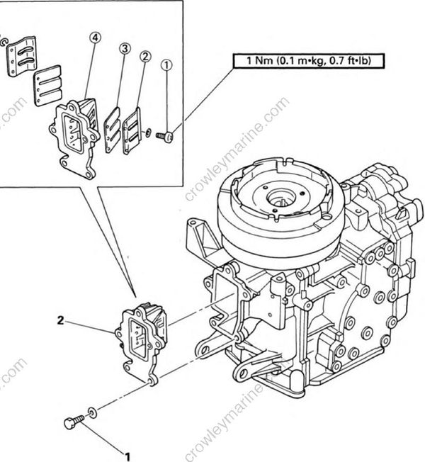
REMOVAL AND INSTALLATION CHART
| Step | Procedure/Part name | Q'ty | Service points |
|---|---|---|---|
| REED VALVE REMOVAL | Follow the left "Step" for removal. | ||
| Carburetor assembly | Refer to the "CARBURETOR REMOVAL" section in chapter 4. | ||
| 1 | Bolt (with washer) | 3 | |
| 2 | Reed valve assembly | 1 | |
| REED VALVE DISASSEMBLY | |||
| (1) | Screw (with washer) | 6 | |
| (2) | Valve stopper | 2 | |
| (3) | Reed valve | 2 | |
| (4) | Reed valve body | 1 | |
| Reverse the removal steps for installation. |
SERVICE POINTS
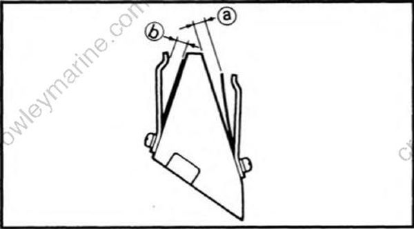
Reed valve inspection
- Inspect:
- Reed valve
Crack/Damage -> Replace.
- Measure:
- Valve bending (a)
Out of specification -> Replace.
Valve bending limit: 0.2 mm (0.01 in)
- Measure:
- Valve stopper height (b)
Out of specification -> Replace.
Valve stopper height:
9.9: except for Europe 0.7 ± 0.1 mm (0.03 ± 0.004 in)
for Europe 1.3 ± 0.1 mm (0.05 ± 0.004 in)
15: 6.0 ± 0.1 mm (0.24 ± 0.004 in)
