

Power unit
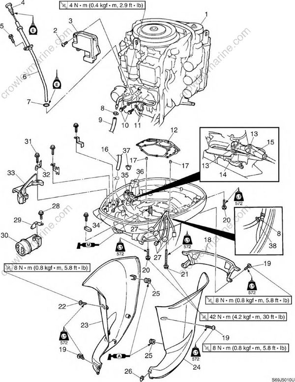
| No. | Part name | Q’ty | Remarks |
|---|---|---|---|
| 1 | Power unit | 1 | |
| 2 | Screw | 4 | |
| 3 | Cover | 1 | |
| 4 | Dipstick | 1 | |
| 5 | Bolt | 1 | M6 x 20 mm |
| 6 | Dipstick guide | 1 | |
| 7 | O-ring | 1 | Not reusable |
| 8 | Plastic tie | 2 | Not reusable |
| 9 | Fuel hose | 1 | |
| 10 | Bolt | 2 | M6 x 10 mm |
| 11 | PTT motor lead | 2 | Sky blue, light green |
| 12 | Gasket | 1 | Not reusable |
| 13 | Clip | 2 | |
| 14 | Shift cable | 1 | |
| 15 | Throttle cable | 1 | |
| 16 | Cooling water pilot hose | 1 | |
| 17 | Dowel pin | 2 | |
| 18 | Upper case cover | 1 | |
| 19 | Bolt | 7 | M6 x 14 mm |
| 20 | Bolt | 7 | M9 x 35 mm |
| 21 | Bolt | 6 | M10 x 140 mm |
| 22 | Bolt | 1 | M6 x 30 mm |
| 23 | Starboard apron | 1 | |
| 24 | Port apron | 1 | |
| 25 | Grommet | 6 | |
| 26 | Nut | 2 | |
| 27 | Fuel pump driver and isolator coupler | 5 | |
| 28 | Bolt | 1 | M6 x 20 mm |
| 29 | Holder | 1 | |
| 30 | Grommet | 1 | |
| 31 | Bolt | 1 | M6 x 30 mm |
| 32 | Holder | 1 | |
| 33 | Retaining plate | 1 | |
| 34 | PTT switch coupler | 1 | |
| 35 | Shift cut switch coupler | 1 | |
| 36 | Neutral switch coupler | 1 | |
| 37 | Clamp | 1 | |
| 38 | Flushing device hose | 1 | Flushing device mode |
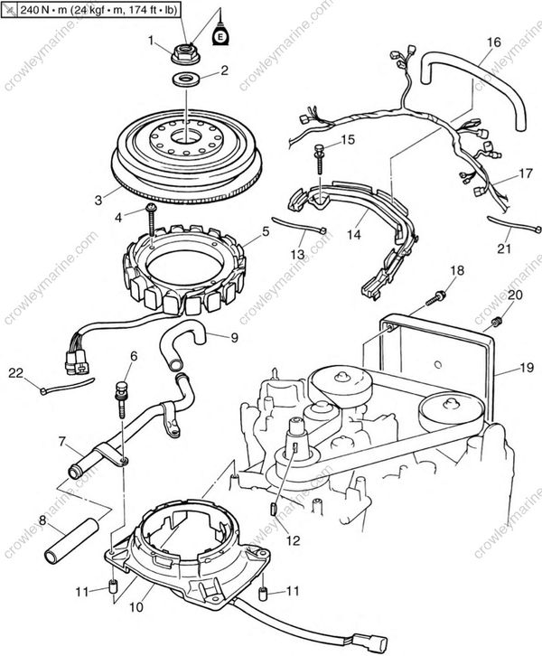
| No. | Part name | Q’ty | Remarks |
|---|---|---|---|
| 1 | Nut | 1 | |
| 2 | Washer | 1 | |
| 3 | Flywheel magnet | 1 | |
| 4 | Screw | 4 | M6 x 30 mm |
| 5 | Stator coil | 1 | |
| 6 | Bolt | 4 | M6 x 35 mm |
| 7 | Blowby hose guide | 1 | |
| 8 | Blowby hose | 1 | |
| 9 | Blowby hose | 1 | |
| 10 | Stator coil bracket | 1 | |
| 11 | Collar | 2 | |
| 12 | Woodruff key | 1 | |
| 13 | Plastic tie | 5 | Not reusable |
| 14 | Wiring harness guide | 1 | |
| 15 | Bolt | 3 | M6 x 35 mm |
| 16 | Idle speed control hose | 1 | |
| 17 | Wiring harness | 1 | |
| 18 | Bolt | 4 | |
| 19 | Ignition coil cover | 1 | |
| 20 | Grommet | 2 | |
| 21 | Plastic tie | 5 | Not reusable |
| 22 | Plastic tie | 2 | Not reusable |
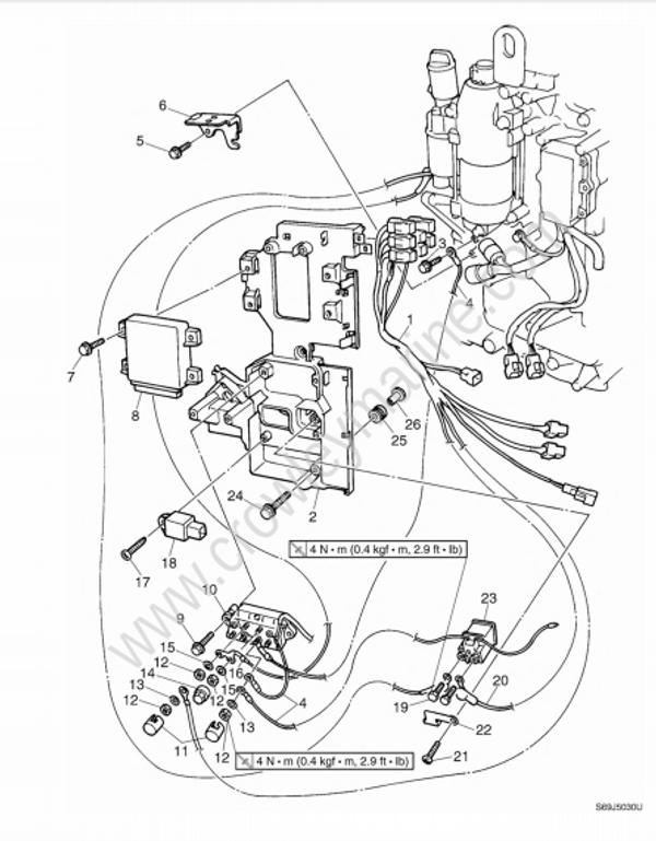
| No. | Part name | Q’ty | Remarks |
|---|---|---|---|
| 1 | Wiring harness | 1 | |
| 2 | Bracket | 1 | |
| 3 | Bolt | 1 | M6 x 20 mm |
| 4 | Ground lead | 3 | |
| 5 | Bolt | 1 | M6 x 16 mm |
| 6 | Bracket | 1 | |
| 7 | Bolt | 4 | M6 x 16 mm |
| 8 | ECM | 1 | |
| 9 | Bolt | 2 | M6 x 25 mm |
| 10 | Power trim and tilt relay | 1 | |
| 11 | Cap | 2 | |
| 12 | Nut | 4 | |
| 13 | Washer | 2 | |
| 14 | Cap | 1 | |
| 15 | Spring washer | 2 | |
| 16 | Battery lead | 1 | Red |
| 17 | Screw | 1 | |
| 18 | Main relay | 1 | |
| 19 | Bolt | 2 | M6 x 10 mm |
| 20 | Starter motor lead | 1 | Brown/white |
| 21 | Screw | 1 | |
| 22 | Holder | 1 | |
| 23 | Starter relay | 1 | |
| 24 | Bolt | 6 | M6 x 28 mm |
| 25 | Grommet | 6 | |
| 26 | Collar | 6 |
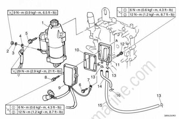
| No. | Part name | Q’ty | Remarks |
|---|---|---|---|
| 1 | Starter motor | 1 | |
| 2 | Nut | 1 | |
| 3 | Spring washer | 1 | |
| 4 | Battery cable | 1 | From terminal and power trim and tilt relay |
| 5 | Bolt | 3 | M8 x 45 mm |
| 6 | Bolt | 1 | M6 x 20 mm |
| 7 | Ground lead | 1 | |
| 8 | Bolt | 2 | M6 x 35 mm |
| 9 | Rectifier Regulator | 1 | |
| 10 | Gasket | 1 | Not reusable |
| 11 | Cover | 1 | |
| 12 | Bolt | 4 | M6 x 25 mm |
| 13 | Clip | 3 | |
| 14 | Cooling water hose | 1 | Out |
| 15 | Cooling water hose | 1 | In |
| 16 | Clip | 1 |
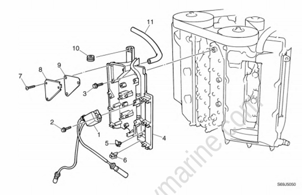
| No. | Part name | Q’ty | Remarks |
|---|---|---|---|
| 1 | Ignition coil | 3 | |
| 2 | Bolt | 6 | M6 x 20 mm |
| 3 | Bolt | 6 | M6 x 20 mm |
| 4 | Bracket | 1 | |
| 5 | Clamp | 3 | |
| 6 | Clamp | 3 | |
| 7 | Screw | 3 | M6 x 20 mm |
| 8 | Plate | 1 | |
| 9 | Gasket | 1 | |
| 10 | Grommet | 1 | |
| 11 | Idle speed control hose | 1 |
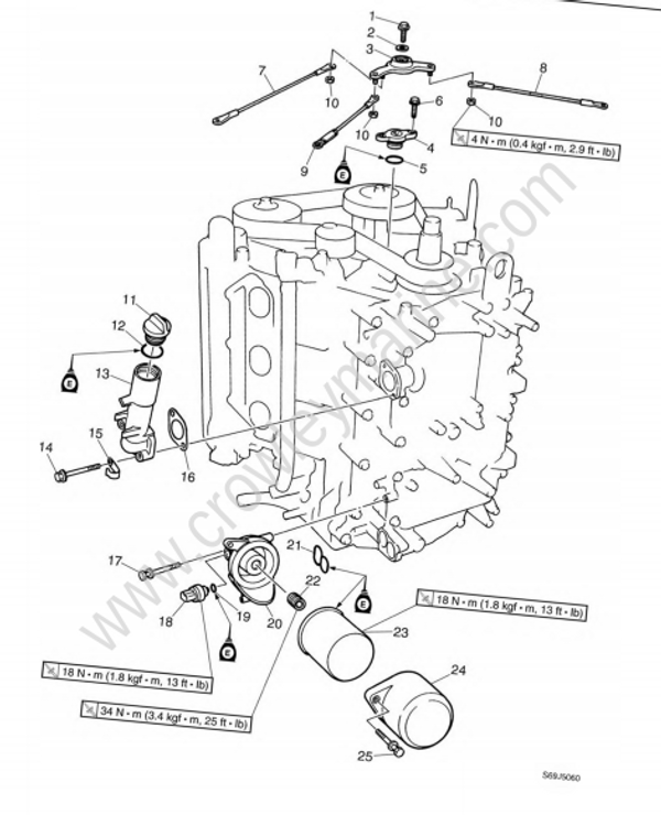
| No. | Part name | Q’ty | Remarks |
|---|---|---|---|
| 1 | Bolt | 1 | M6 x 30 mm |
| 2 | Washer | 1 | |
| 3 | Link rod arm | 1 | |
| 4 | Plug | 1 | |
| 5 | O-ring | 1 | Not reusable |
| 6 | Bolt | 2 | M6 x 20 mm |
| 7 | Link rod | 1 | Long |
| 8 | Link rod | 1 | Short |
| 9 | Link rod | 1 | |
| 10 | Nut | 3 | |
| 11 | Oil filler cap | 1 | |
| 12 | O-ring | 1 | Not reusable |
| 13 | Oil filler neck | 1 | |
| 14 | Bolt | 2 | M6 x 45 mm |
| 15 | Clamp | 1 | |
| 16 | Gasket | 1 | Not reusable |
| 17 | Bolt | 3 | M6 x 45 mm |
| 18 | Oil pressure sensor | 1 | |
| 19 | O-ring | 1 | Not reusable |
| 20 | Oil filter bracket | 1 | |
| 21 | Gasket | 1 | Not reusable |
| 22 | Bolt | 1 | |
| 23 | Oil filter | 1 | |
| 24 | Oil filter cover | 1 | |
| 25 | Bolt | 1 | M6 x 40 mm |
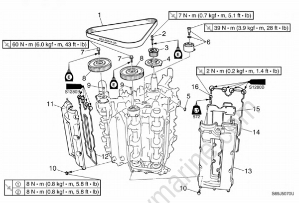
| No. | Part name | Q’ty | Remarks |
|---|---|---|---|
| 1 | Timing belt | 1 | |
| 2 | Bolt | 4 | M5 x 45 mm |
| 3 | Drive sprocket | 1 | |
| 4 | Plate | 1 | |
| 5 | Woodruff key | 1 | |
| 6 | Timing belt tensioner | 1 | |
| 7 | Bolt | 2 | M10 x 35 mm |
| 8 | Driven sprocket | 2 | |
| 9 | Dowel pin | 2 | |
| 10 | Bolt | 28 | M6 x 30 mm |
| 11 | Port cylinder head cover | 1 | |
| 12 | Gasket | 1 | Not reusable |
| 13 | Starboard cylinder head cover | 1 | |
| 14 | Gasket | 1 | Not reusable |
| 15 | Plate | 1 | |
| 16 | Screw | 8 | M4 x 8 mm |
Checking the compression pressure
Start the engine, warm it up for 5 minutes, and then turn it off.
Remove the clip from the engine stop lanyard switch on the remote control box.
Remove the ignition coil cover and all spark plugs, and then install the special service tools to each spark plug hole.
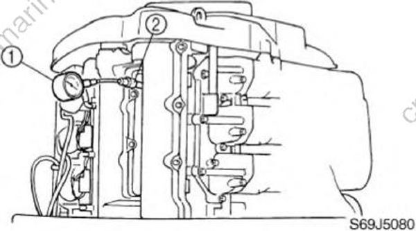
CAUTION:
Before removing the spark plugs, blow compressed air in the spark plug well to clear out any dirt or dust that may fall into the cylinder.
Compression gauge (1) : YU-33223-1
Compression gauge extension (2) : YB-06563
- Fully open the throttle, crank the engine until the reading on the compression gauge stabilizes, and then check the compression pressure.
Minimum compression pressure (reference data) : 880 kPa (8.8 kgf/cm2,125 psi)
- If the compression pressure is below specification and the compression pressure for each cylinder is unbalanced, add a small amount of engine oil to the cylinder, and then check the pressure again.
NOTE:
If the compression pressure increases, check the piston and piston rings for wear. Replace if necessary.
If the compression pressure does not increase, check the valve clearance, valve, valve seat, cylinder sleeve, cylinder head gasket, and cylinder head. Adjust or replace if necessary.
Checking the oil pressure
Place a rag under the oil pressure sensor.
Remove the intake silencer and oil pressure sensor, and then install an oil pressure gauge (1) to the oil pressure sensor installation hole.
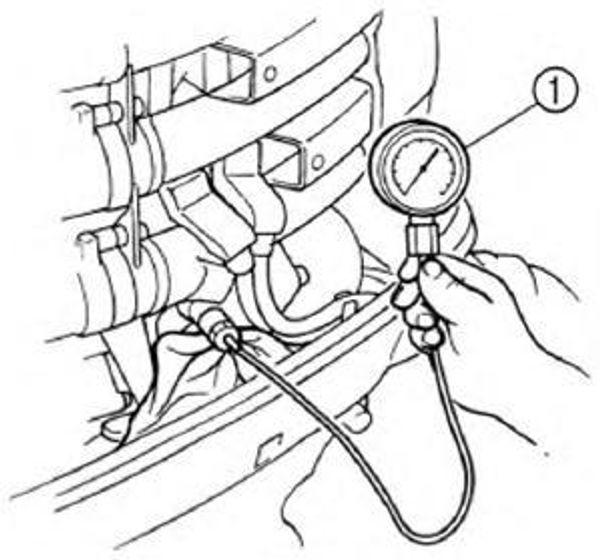
NOTE: Use a pressure gauge with an adapter that has a 1/8 pitch thread.
- Install the intake silencer.
CAUTION:
Do not start the engine when the intake silencer is not installed.
Start the engine and warm it up for 5 minutes.
Check the oil pressure. Check the oil pump, oil leakage, and oil strainer if out of specification.
Oil pressure (reference data) : 650 kPa (6.5 kgf/cm2, 92.4 psi) at idle speed (700 r/min)
Checking the oil pressure sensor
Connect the test harness (3 pins) to the oil pressure sensor.
Start the engine and warm it up for 5 minutes.
Measure the oil pressure sensor input voltage. Check the wiring harness connection or replace the ECM if out of specification.
Measure the oil pressure sensor output voltage. Replace if out of specification.
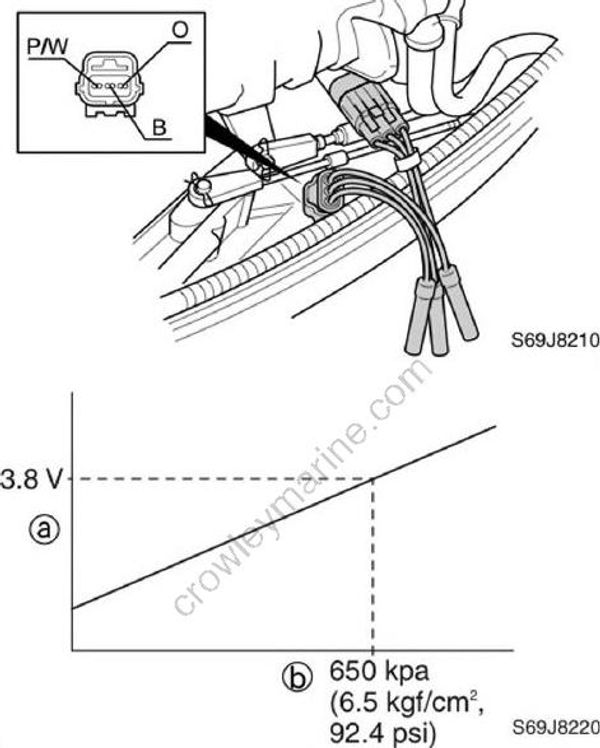
(a) : Output voltage
(b) : Oil pressure
Test harness (3 pins) : YB-06769
On Oil pressure sensor input voltage : Orange (O) - Black (B) 5 V
Oil pressure sensor output voltage (reference data):
Pink/white (P/W) - Black (B)
3.8 V at idle speed (700 r/min)
Checking the valve clearance
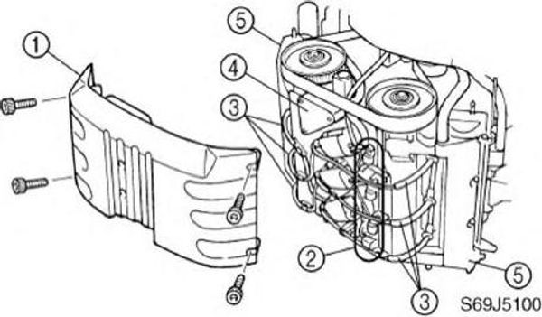
Remove the flywheel magnet cover and ignition coil cover (1).
Disconnect the ignition coil couplers (2) and spark plug caps (3), and remove the ignition coil bracket (4), spark plugs, and cylinder head covers (5).
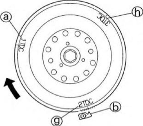
- Turn the flywheel magnet clockwise and align the “1TDC” mark (a) on the flywheel magnet with the pointer (b) and check that “I” marks (c) and (d) on the driven sprockets are aligned with marks (e) and (f).
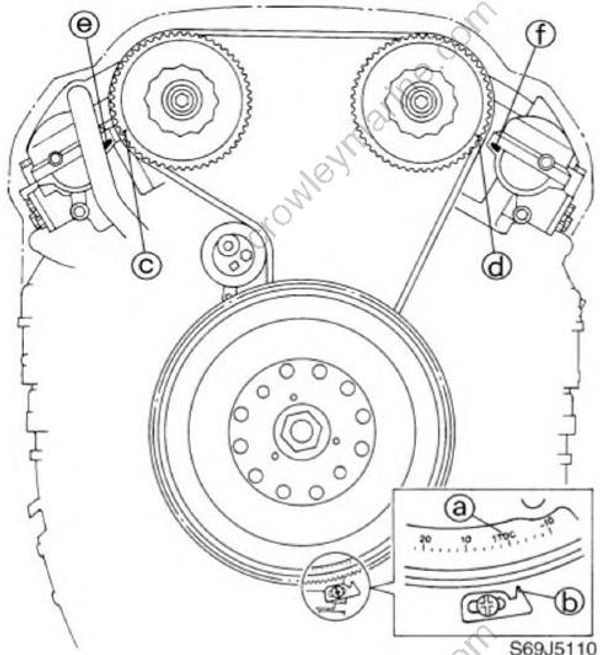
NOTE: Do not turn the flywheel magnet counter clockwise.
Check the intake and exhaust valve clearance for cylinder # 4.
Turn the flywheel magnet an additional 120° clockwise and align the “2TDC” mark (g) on the flywheel magnet with the pointer (b).
Check the intake and exhaust valve clearance for cylinder # 5.
Turn the flywheel magnet an additional 120° clockwise and align the “3TDC” mark (h) on the flywheel magnet with the pointer (b).
Check the intake and exhaust valve clearance for cylinder # 6.
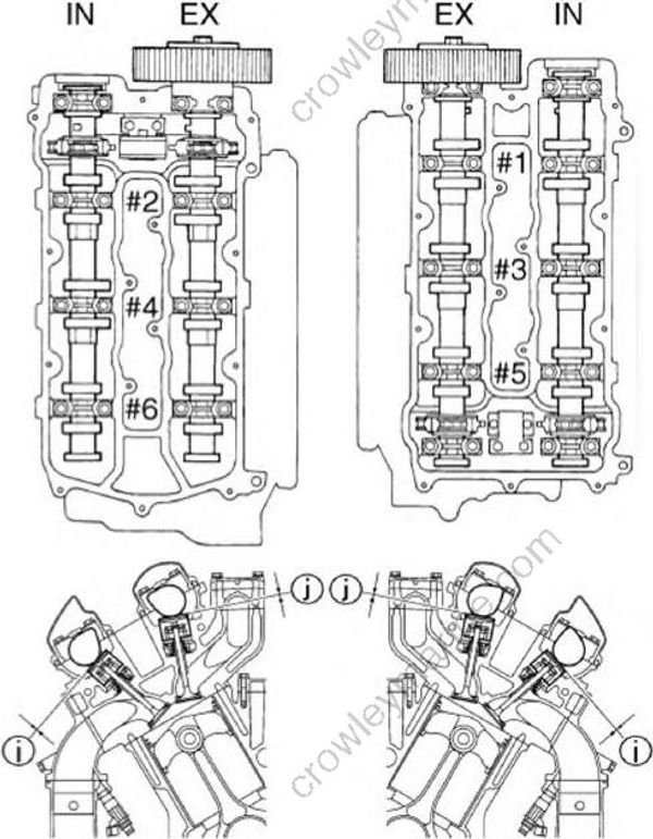
- Similarly, check the valve clearance of cylinders # 1, # 2, and # 3 in order, and be sure to turn the flywheel magnet 120° clockwise each time. Adjust if out of specification.
NOTE:
Check the valve clearance when the engine is cold.
Note the measurement.
Valve clearance: Intake (i) : 0.20 ± 0.03 mm (0.008 ± 0.001 in)
Exhaust (j) : 0.34 ± 0.03 mm (0.013 ± 0.001 in)
Turn the flywheel magnet an additional 120° clockwise and align the “1TDC” mark on the flywheel magnet with the pointer, and check that the “I” marks on the driven sprockets are aligned with the alignment marks on the cylinder head.
Remove the flywheel magnet.
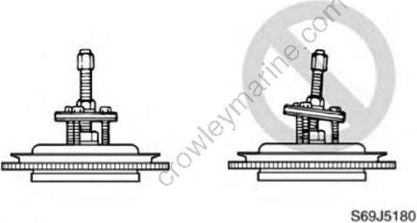
CAUTION:
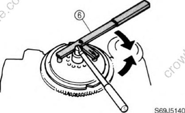
Apply force in the direction of the arrows shown, to prevent the flywheel holder from slipping off easily.
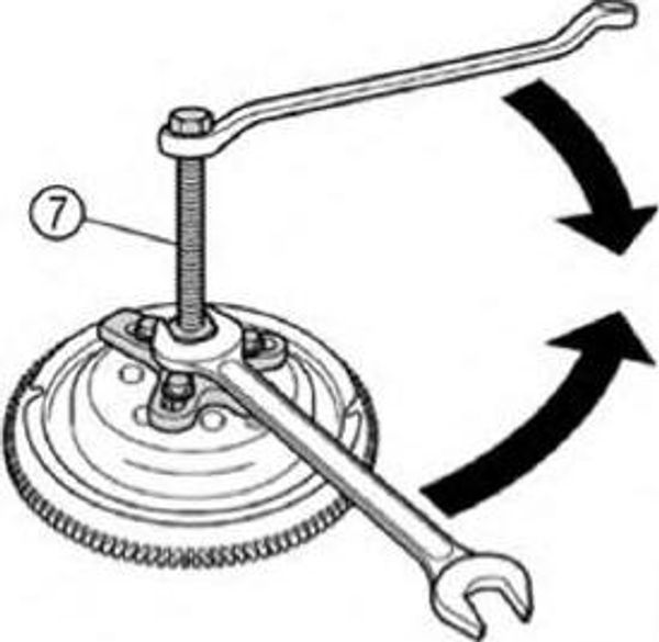
To prevent damage to the engine or tools, screw in the flywheel puller set bolts evenly and completely so that the flywheel puller plate is parallel to the flywheel magnet.
NOTE:
Apply force to the crankshaft end until the fly wheel magnet comes off the tapered portion of the crankshaft.
Flywheel magnet holder (6) : YB-06139
Universal puller (7) : YB-06117
- Remove the wiring harness guide bolts.
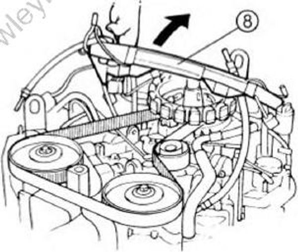
NOTE:
Move the wiring harness guide (8) to a position that will make servicing easy.
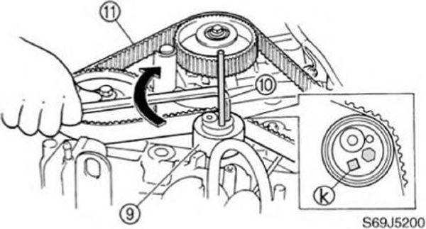
- Using a hexagon wrench, turn the timing belt tensioner (9) clockwise to push the timing belt, increase strength gradually, and then insert a o5.0 mm (0.2 in) pin (10) into the hole (k).
NOTE:
Leave the pin inserted into the timing belt tensioner until the timing belt has been installed.
- Remove the timing belt (11) from the driven sprockets.
- Remove the driven sprockets.
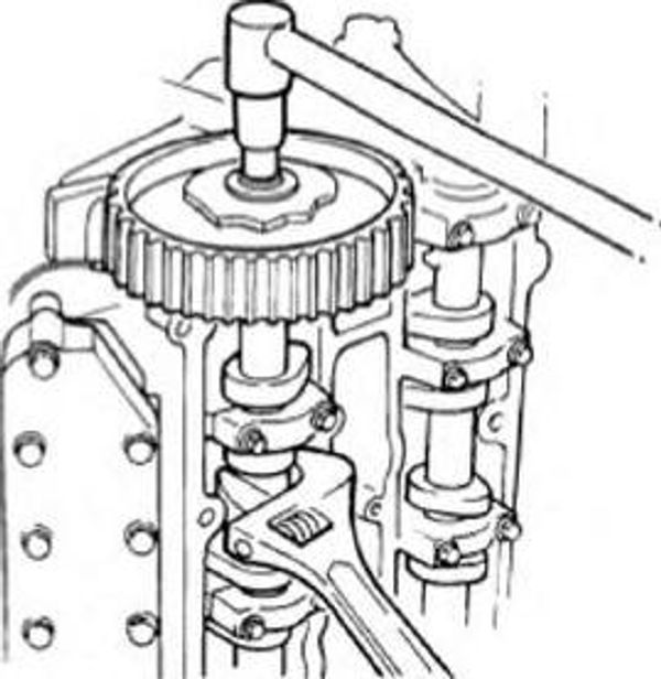
NOTE:
Hold the camshaft with a wrench, and be careful not to damage the driven sprocket.
- Remove the timing chain tensioners (12), then the camshaft caps in the order shown in the illustration.
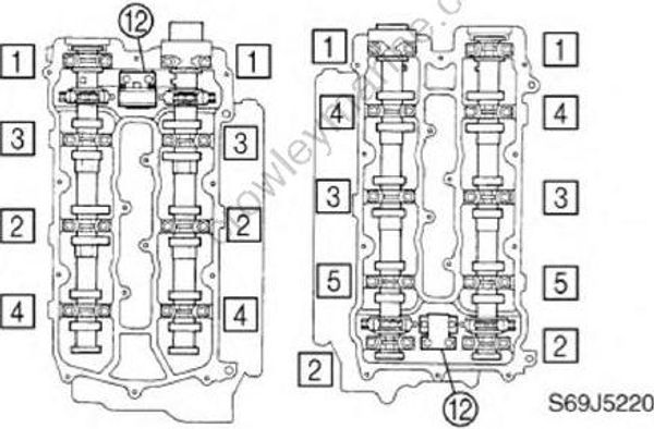
Remove the camshafts and timing chains.
Remove the valve shim (13) from the valve lifter (14) using compressed air.
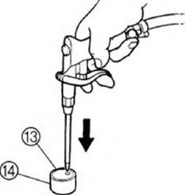
NOTE:
Do not mix the valve train parts. Keep them organized in their proper groups.
Measure the valve shim thickness with a micrometer, and then note the measurement.
Select the necessary valve shim by calculating its thickness with the following formula.
Necessary valve shim thickness =
Removed valve shim thickness +
Measured valve clearance Specified valve clearance
Example:
If the “Removed valve shim thickness” is 2.10 mm, the “Checked valve clearance” is 0.30 mm and the “Specified valve clearance” is 0.20 mm, then the “Necessary valve shim thickness” = 2.10 + 0.30 0.20 = 2.20 mm
Install the necessary valve shim into the valve lifter.
Align the projection (wide one) (l) on the camshaft sprockets to the alignment plate (gold) (m) on the timing chain, and then install the camshafts to the cylinder head with new oil seals.
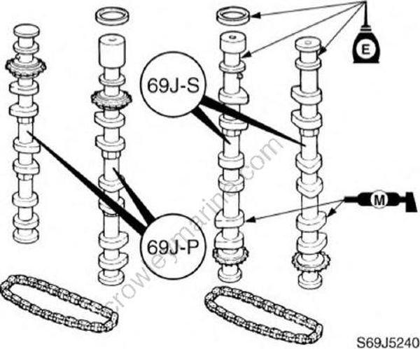
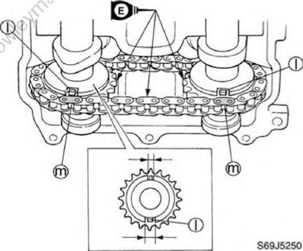
Install the camshaft caps, and then tighten them to the specified torque in the order shown in the illustration.
Install the timing chain tensioners (12), and then tighten the bolts to the specified torque in the sequence shown.
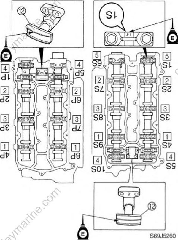
NOTE:
Install the camshaft caps in the proper position as shown and with the stamped numbers facing upside down.
Apply engine oil to the camshaft cap bolts before installation.
Camshaft cap bolt:
1st: 8 N-m (0.8 kgf-m, 5.8 ft-lb)
2nd: 17 N-m (1.7 kgf-m, 12 ft-lb)
Timing chain tensioner bolt: 12 N-m (1.2 kgf-m, 8.7 ft-lb)
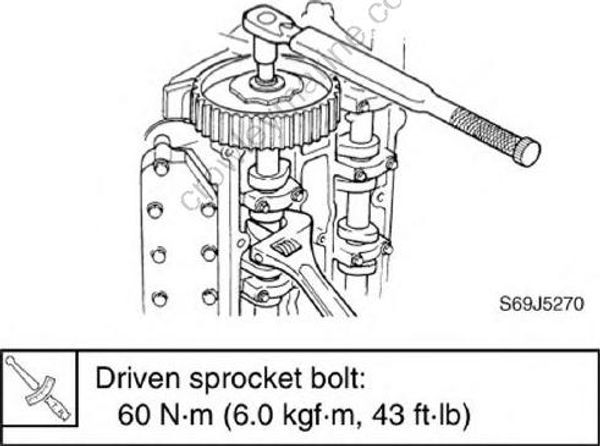
- Install the driven sprockets, and then tighten the bolts to the specified torque.
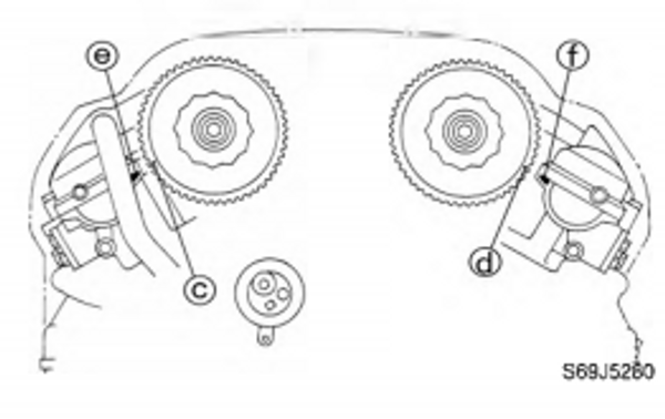
- Turn the driven sprockets clockwise and align “I” marks (c) and (d) on the driven sprockets with marks (e) and (f) .
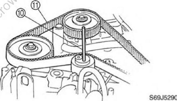
- Install the timing belt (11), turn the belt from the drive sprocket side a half turn counterclockwise to align it, and then remove the pin (10).
- Install the Woodruff key.
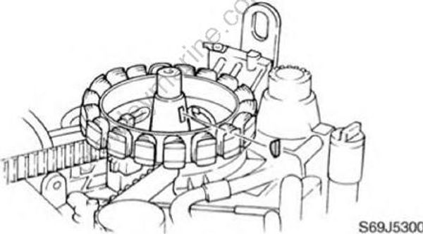
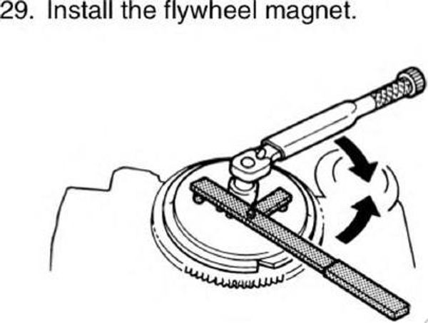
CAUTION:
Apply force in the direction of the arrows shown, to prevent the flywheel holder from slipping off easily.
NOTE:
Apply engine oil to the flywheel magnet nut before installation
Flywheel magnet holder : YB-06139
Flywheel magnet nut : 240 N-m (24 kgf-m, 174 ft-lb)
- Turn the flywheel magnet clockwise two turns, and then check that all alignment marks are aligned.
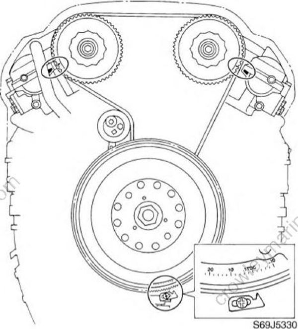
NOTE: Do not turn the flywheel magnet counter clockwise.
Check each valve clearance and adjust if necessary.
Install the spark plugs, and then tighten them to the specified torque.
Install the cylinder head cover bolts, and then tighten them to the specified torques in two stages.
Spark plug : 25 N-m (2.5 kgf-m, 18 ft-lb)
Cylinder head cover bolt:
1st : 8 N-m (0.8 kgf-m, 5.8 ft-lb)
2nd : 8 N-m (0.8 kgf-m, 5.8 ft-lb)
Install the ignition coil bracket, and connect the ignition coil couplers and spark plug caps.
Install the ignition coil cover, wiring harness guide, and flywheel magnet cover.
Replacing the timing belt
Remove the flywheel magnet cover, ignition coil cover, and intake silencer.
Turn the flywheel magnet clockwise and align the “1TDC” mark (a) on the flywheel magnet with the pointer (b), and check that “I” marks (c) and (d) on the driven sprockets are aligned with marks (e) and (f).
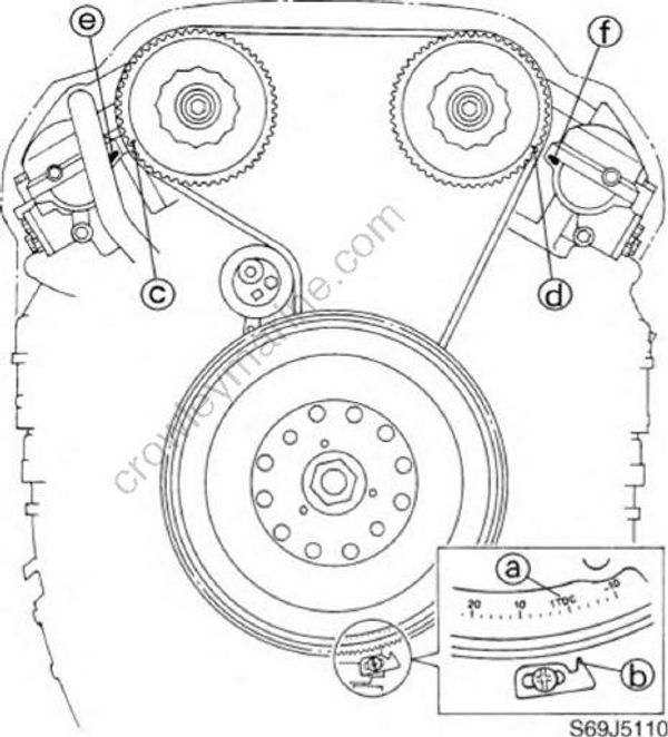
NOTE: Do not turn the flywheel magnet counter clockwise.
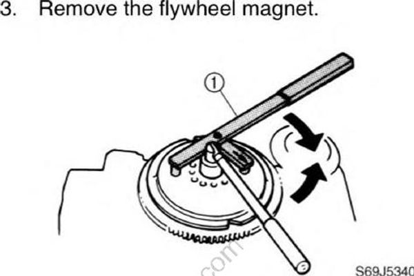
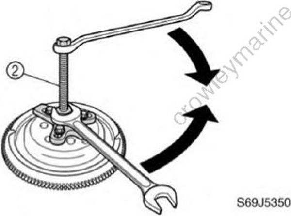
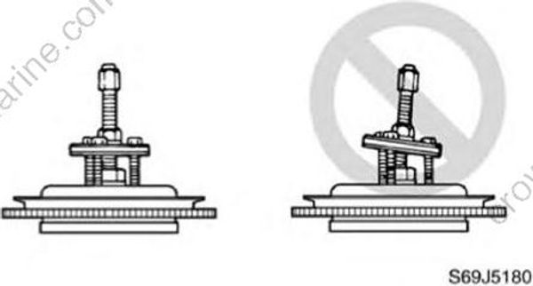
CAUTION:
Apply force in the direction of the arrows shown, to prevent the flywheel holder from slipping off easily.
To prevent damage to the engine or tools, screw in the flywheel puller set bolts evenly and completely so that the flywheel puller plate is parallel to the flywheel magnet.
NOTE:
Apply force to the crankshaft end until the flywheel magnet comes off the tapered portion of the crankshaft.
Flywheel magnet holder (1) : YB-06139
Universal puller (2) : YB-06117
Disconnect the ignition coil couplers, idle speed control coupler, intake air pressure sensor coupler, throttle position sensor coupler, thermoswitch leads, idle speed control hose, high-pressure fuel hoses, neutral switch coupler, shift cut switch coupler, and starboard fuel injector couplers.
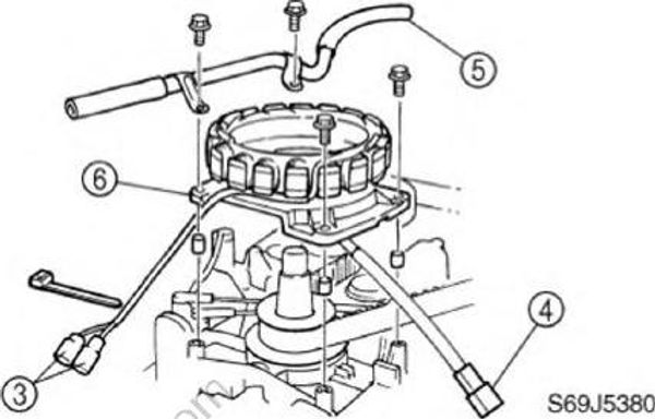
Disconnect the stator coil couplers (3) and pulser coil coupler (4), and remove the blowby hose (5) and stator coil bracket (6).
- Remove the wiring harness guide bolts.
NOTE:
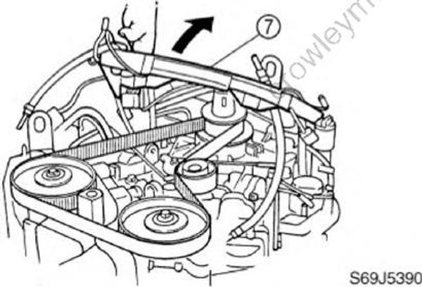
Move the wiring harness guide (7) to a position that will make servicing easy.
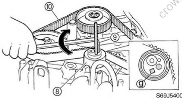
- Using a hexagon wrench, turn the timing belt tensioner (8) clockwise to push the timing belt, increase strength gradually, and then insert a o5.0 mm (0.2 in) pin (9) into the hole (g).
NOTE:
Leave the pin inserted into the timing belt tensioner until the timing belt has been installed.
- Remove the timing belt (10) from the driven sprocket side.
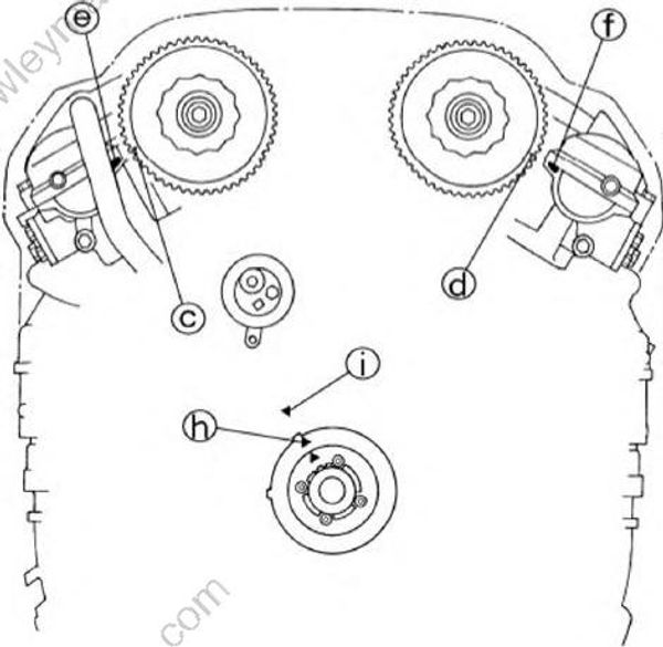
- Check that “I” marks (c) and (d) on the driven sprockets are aligned with marks (e) and (f), and that the “▲” mark (h) on the plate is aligned with the “▲” mark (i) on the cylinder block. Align if necessary.
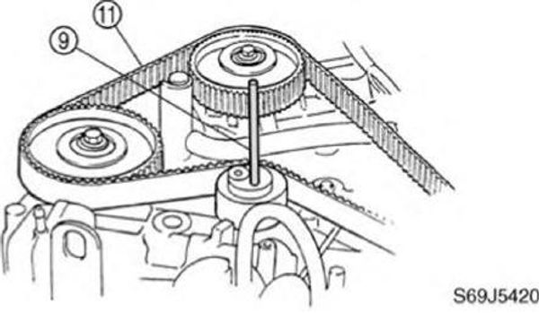
- Install the timing belt (11) from the drive sprocket side with its part number in the upright position, turn the belt a half turn counterclockwise to align it, and then remove the pin (9).
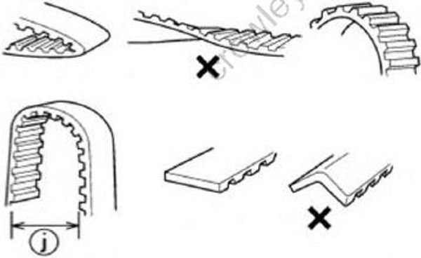
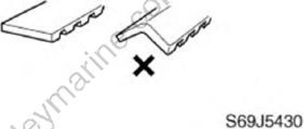
CAUTION:
Do not twist, turn inside out, or bend the timing belt beyond the maximum limit of 25 mm (1.0 in) (j), otherwise it may be damaged.
Do not get oil or grease on the timing belt
- Turn the drive sprocket clockwise two turns, and then check that all alignment marks are aligned.
NOTE: Do not turn the drive sprocket counterclock wise.
Install the wiring harness guide, stator coil bracket, and blowby hose, and connect the pulser coil coupler and stator coil couplers.
Connect all couplers, leads, and hoses.
Install the Woodruff key.
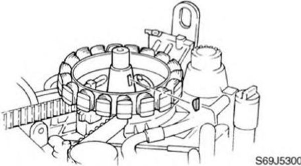
- Install the flywheel magnet.
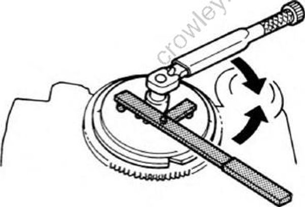
CAUTION:
Apply force in the direction of the arrows shown, to prevent the flywheel holder from slipping off easily.
NOTE: Apply engine oil to the flywheel magnet nut before installation.
Flywheel magnet holder : YB-06139
Flywheel magnet nut : 240 N m (24 kgf-m, 174 ft-lb)
- Install the intake silencer, ignition coil cover, and flywheel magnet cover.
Removing the power unit
Remove the flywheel magnet cover and intake silencer.
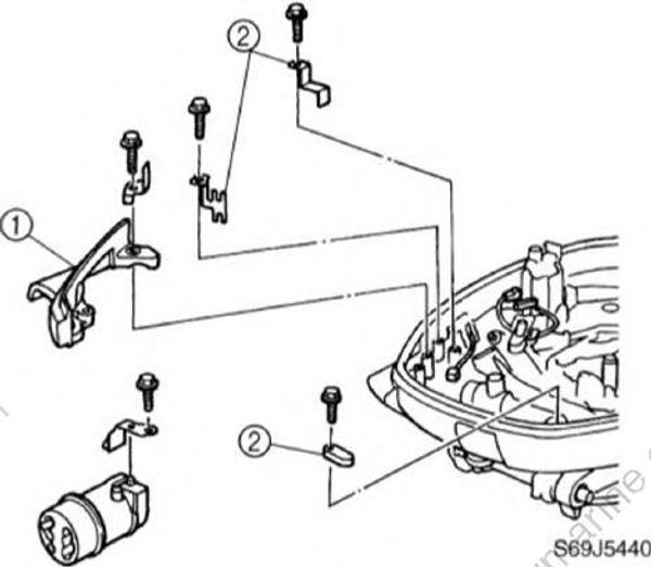
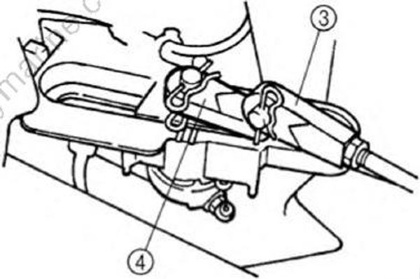
Remove the retaining plate (1) and holders (2), and then disconnect the throttle cable (4) and shift cable (4).
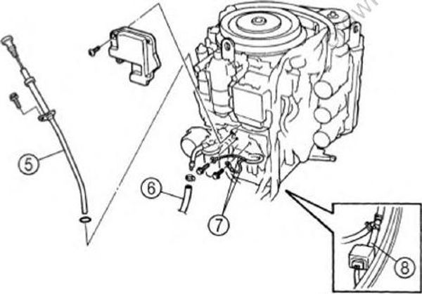
- Remove the dipstick guide (5), and disconnect the fuel hose (6), PTT motor leads (7), and flushing device hose (flushing device model) (8).
- Disconnect the fuel pump driver and isolator couplers, PTT switch coupler, shift cut switch coupler, neutral switch coupler, trim sensor coupler, and cooling water pilot hose.
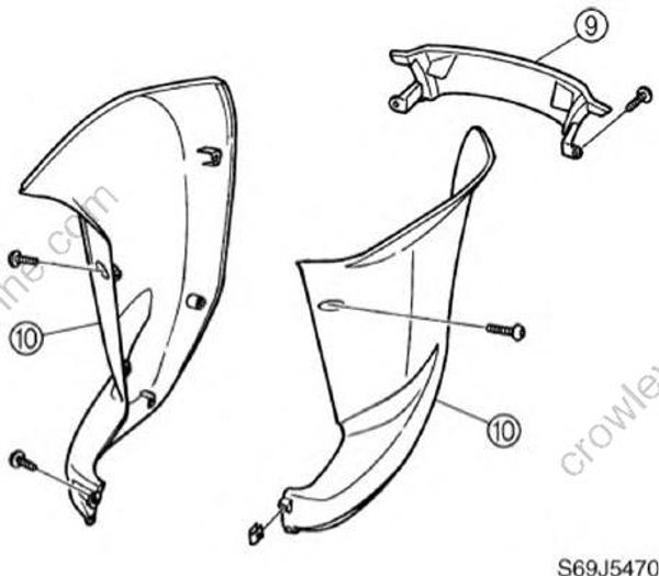
- Remove the upper case cover (9) and aprons (10).
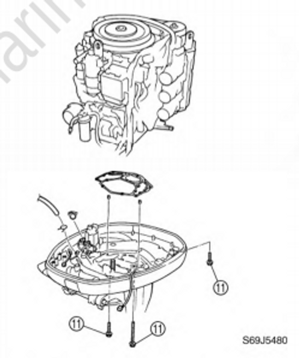
- Remove the power unit by removing the bolts (11).
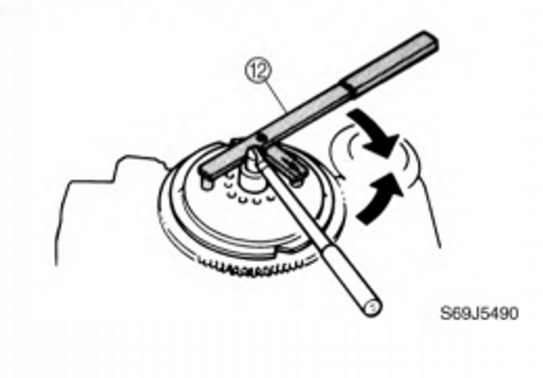
- Remove the flywheel magnet.
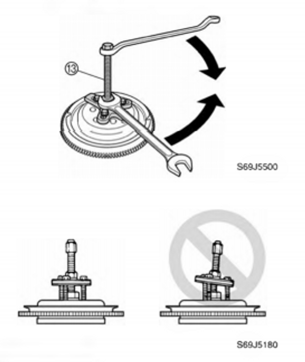
CAUTION:
Apply force in the direction of the arrows shown, to prevent the flywheel holder from slipping off easily.
To prevent damage to the engine or tools, screw in the flywheel puller set bolts evenly and completely so that the flywheel puller plate is parallel to the flywheel magnet.
NOTE:
Apply force to the crankshaft end until the flywheel magnet comes off the tapered portion of the crankshaft.
Flywheel magnet holder (12) : YB-06139
Universal puller (13) : YB-06117
Removing the oil filter
- Place a rag under the oil filter, and then remove the filter using a 72.5 mm (2.9 in) oil filter wrench.
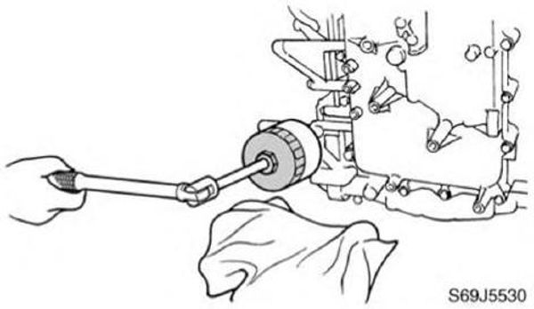
NOTE: Be sure to clean up any oil spills.
Removing the timing belt and sprockets
- Turn the drive sprocket clockwise and align the “▲” mark (a) on the plate with the “▲” mark (b) on the cylinder block, and check that “I” marks (c) and (d) on the driven sprockets are aligned with marks (e) and (f).
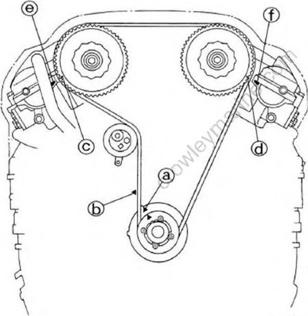
NOTE: Do not turn the drive sprocket counterclock wise.
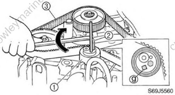
Using a hexagon wrench, turn the timing belt tensioner (1) clockwise to push the timing belt, increase strength gradually, and then insert a o5.0 mm (0.2 in) pin (2) into the hole (g).
Remove the timing belt (3) from the driven sprocket side.
Remove the pin and timing belt tensioner.
Remove the drive sprocket and plate.
Remove the cylinder head covers, and then remove the driven sprockets.
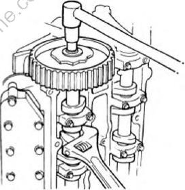
NOTE:
Hold the camshaft with a wrench, and be careful not to damage the driven sprocket.
Checking the timing belt and sprockets
- Check the interior and exterior of the timing belt for cracks, damage, or wear. Replace if necessary.
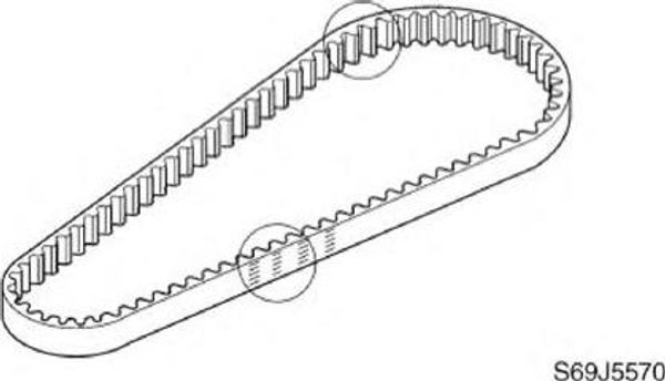
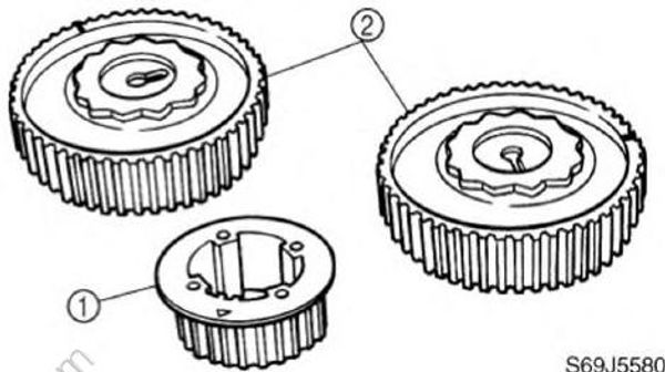
- Check the drive sprocket (1) and driven sprockets (2) for cracks, damage, or wear. Replace if necessary.
Installing the sprockets and timing belt
Install the driven sprockets (1), and then tighten the bolts to the specified torque.
Check that “I” marks (a) and (b) on the driven sprockets are aligned with marks (c) and (d). Align if necessary.
Install the new gaskets, cylinder head cover (2), and then tighten the bolts to the specified torques in two stages.
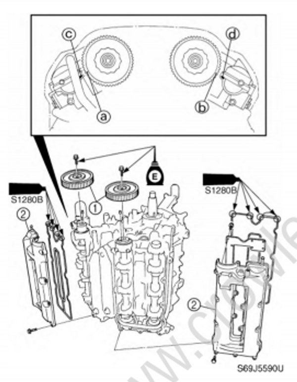
Driven sprocket bolt : 60 N-m (6.0 kgf-m, 43 ft-lb)
Cylinder head cover bolt:
1st: 8 N-m (0.8 kgf-m, 5.8 ft-lb)
2nd: 8 N-m (0.8 kgf-m, 5.8 ft-lb)
Install the drive sprocket (3) and timing belt tensioner (4), and then tighten the bolts to the specified torques.
Check that the “▲” mark (e) on the plate is aligned with the “▲” mark (f) on the cylinder block. Align if necessary.
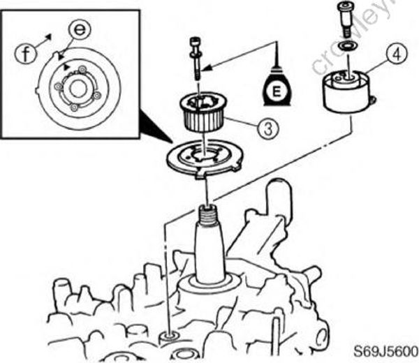
Drive sprocket bolt : 7 N-m (0.7 kgf-m, 5.1 ft-lb)
Timing belt tensioner bolt : 39 N-m (3.9 kgf-m, 28 ft-lb)
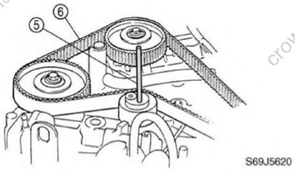
- Using a hexagon wrench, turn the timing belt tensioner (4) clockwise to push the timing belt, increase strength gradually, and then insert a o5.0 mm (0.2 in) pin (5) into the hole (g).
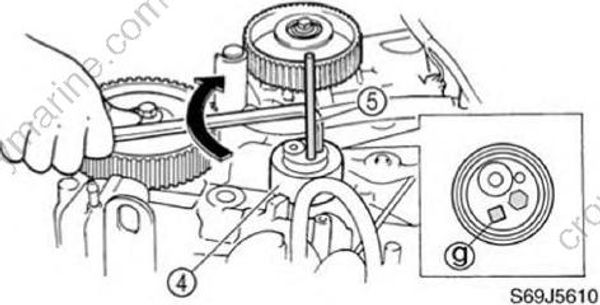
- Install the timing belt (6) from the drive sprocket side with its part number in the upright position, turn the belt a half turn counterclockwise to align it, and then remove the pin (5).
- Turn the drive sprocket clockwise two turns, and then check that the alignment marks are aligned.
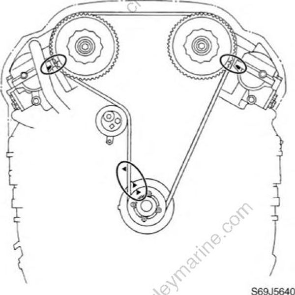
NOTE: Do not turn the drive sprocket counterclock wise.
