Power unit
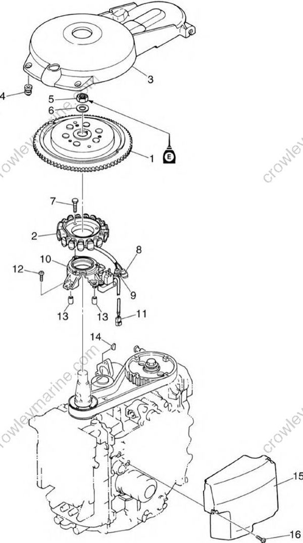
| No. | Part name | Q’ty | Remarks | Tightening torques | Tightening torques | Tightening torques | Tightening torques |
|---|---|---|---|---|---|---|---|
| Stage | N⋅m | kgf⋅m | ft⋅lb | ||||
| 1 | Flywheel magnet | 1 | |||||
| 2 | Stator coil | 1 | |||||
| 3 | Cover | 1 | |||||
| 4 | Grommet | 2 | |||||
| 5 | Nut | 1 | 160 | 16 | 116 | ||
| 6 | Washer | 1 | |||||
| 7 | Bolt | 3 | M6 x 25 mm | ||||
| 8 | Lighting coil coupler | 1 | |||||
| 9 | Charge coil coupler | 1 | |||||
| 10 | Stator base | 1 | |||||
| 11 | Pulser coil coupler | 1 | |||||
| 12 | Screw | 4 | M6 x 24 mm | 4 | 0.4 | 2.9 | |
| 13 | Dowel pin | 2 | |||||
| 14 | Woodruff key | 1 | |||||
| 15 | Cover | 1 | |||||
| 16 | Screw | 3 | M6 x 35 mm | 3 | 0.3 | 2.2 |
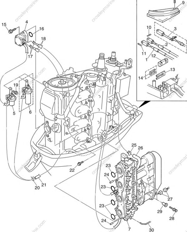
| No. | Part name | Q’ty | Remarks | Tightening torques | Tightening torques | Tightening torques | Tightening torques |
|---|---|---|---|---|---|---|---|
| Stage | N⋅m | kgf⋅m | ft⋅lb | ||||
| 1 | Throttle cable | 1 | |||||
| 2 | Shift cable | 1 | F50/F50A, T50/FT50B | ||||
| 3 | Shift cable | 1 | FT50C | ||||
| 4 | Fuel pump | 1 | |||||
| 5 | Fuel filter assembly | 1 | F50/F50A | ||||
| 6 | Fuel filter assembly | 1 | T50/FT50B, FT50C | ||||
| 7 | Carburetor assembly | 1 | |||||
| 8 | Bolt | 3 | M6 x 20 mm | ||||
| 9 | Plate | 1 | |||||
| 10 | Clip | 1 | |||||
| 11 | Clip | 1 | |||||
| 12 | Grommet | 1 | |||||
| 13 | Holder | 1 | F50/F50A, T50/FT50B | ||||
| 14 | Holder | 1 | FT50C | ||||
| 15 | Bolt | 2 | |||||
| 16 | O-ring | 1 | Not reusbale | ||||
| 17 | Clip | 2 | |||||
| 18 | Fuel hose | 2 | Fuel pump-to-carburetor | ||||
| 19 | Bolt | 1 | |||||
| 20 | Clip | 1 | |||||
| 21 | Fuel hose | 1 | Fuel filter-to-fuel joint | ||||
| 22 | Bolt | 8 | |||||
| 23 | O-ring | 4 | Not reusable | ||||
| 24 | Dowel pin | 2 | |||||
| 25 | Clip | 1 | |||||
| 26 | Blowby hose | 1 | |||||
| 27 | Prime Start coupler | 1 | |||||
| 28 | Bolt | 2 | M6 x 30 mm | ||||
| 29 | Collar | 2 | |||||
| 30 | Throttle link rod | 1 |
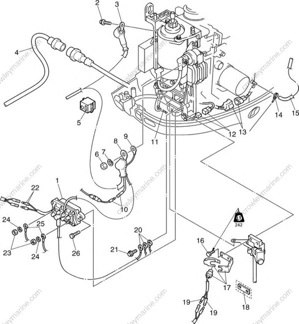
| No. | Part name | Q’ty | Remarks | Tightening torques | Tightening torques | Tightening torques | Tightening torques |
|---|---|---|---|---|---|---|---|
| Stage | N⋅m | kgf⋅m | ft⋅lb | ||||
| 1 | Power trim and tilt relay | 1 | EHT/ET models | ||||
| 2 | Bolt | 1 | M8 x 16 mm | 9 | 0.9 | 6.5 | |
| 3 | Negative battery lead | 1 | |||||
| 4 | Wiring harness extension | 1 | |||||
| 5 | Grommet | 1 | |||||
| 6 | Nut | 1 | 7 | 0.7 | 5.1 | ||
| 7 | Spring washer | 1 | |||||
| 8 | Positive battery lead | 1 | |||||
| 9 | PTT relay positive lead | 1 | EHT/ET models | ||||
| 10 | Fuse holder lead | 1 | |||||
| 11 | Clip | 1 | |||||
| 12 | Warning indicator coupler | 1 | EHD/EHT models | ||||
| 13 | Trailer switch coupler | 1 | EHT/ET models | ||||
| 14 | Plastic tie | 1 | Not reusable | ||||
| 15 | Pilot water hose | 1 | |||||
| 16 | Bolt | 2 | M6 x 20 mm | ||||
| 17 | Neutral switch | 1 | Tiller handle models | ||||
| 18 | Plate | 1 | Remote control models | ||||
| 19 | Neutral switch lead | 2 | Tiller handle models | ||||
| 20 | Ground lead | 3 | |||||
| 21 | Bolt | 1 | M6 x 12 mm | ||||
| 22 | PTT relay lead | 2 | EHT/ET models | ||||
| 23 | Nut | 2 | EHT/ET models | ||||
| 24 | Spring washer | 2 | EHT/ET models | ||||
| 25 | PTT motor lead | 2 | EHT/ET models | ||||
| Green, blue | |||||||
| 26 | Bolt | 2 | M6 x 20 mm | ||||
| EHT/ET models |
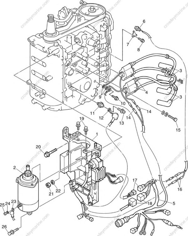
| No | Part name | Q’ty | Remarks | Tightening torques | Tightening torques | Tightening torques | Tightening torques |
|---|---|---|---|---|---|---|---|
| Stage | N⋅m | kgf⋅m | ft⋅lb | ||||
| 1 | Bracket | 1 | |||||
| 2 | Starter motor | 1 | |||||
| 3 | Spark plug cap | 4 | |||||
| 4 | Ignition coil | 2 | |||||
| 5 | Wiring harness | 1 | |||||
| 6 | Thermoswitch | 1 | |||||
| 7 | Holder | 1 | |||||
| 8 | Bolt | 1 | M6 x 12 mm | ||||
| 9 | Ground lead | 3 | |||||
| 10 | Bolt | 1 | M6 x 12 mm | ||||
| 11 | Oil pressure switch | 1 | 9 | 0.9 | 6.5 | ||
| 12 | Oil pressure switch lead | 1 | |||||
| 13 | Screw | 1 | 2 | 0.2 | 1.4 | ||
| 14 | Ignition coil lead | 2 | |||||
| 15 | Bolt | 4 | M6 x 30 mm | 7 | 0.7 | 5.1 | |
| 16 | Thermoswitch lead | 2 | |||||
| 17 | Rectifier Regulator coupler | 1 | |||||
| 18 | CDI unit coupler | 1 | |||||
| 19 | Bolt | 2 | M8 x 25 mm | 30 | 3.0 | 22 | |
| 20 | Bolt | 3 | M8 x 35 mm | ||||
| 21 | Nut | 1 | |||||
| 22 | Spring washer | 1 | |||||
| 23 | Starter motor lead | 1 | |||||
| 24 | Spring washer | 1 | |||||
| 25 | Nut | 1 | 7 | 0.7 | 5.1 | ||
| 26 | Bolt | 1 | M8 x 45 mm | 30 | 3.0 | 22 |
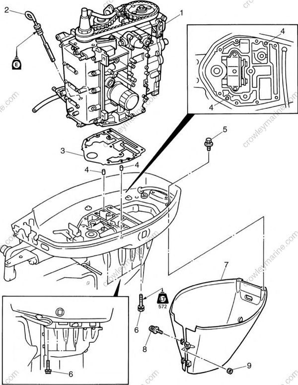
| No. | Part name | Q’ty | Remarks | Tightening torques | Tightening torques | Tightening torques | Tightening torques |
|---|---|---|---|---|---|---|---|
| Stage | N⋅m | kgf⋅m | ft⋅lb | ||||
| 1 | Power unit | 1 | |||||
| 2 | Engine oil dipstick | 1 | |||||
| 3 | Gasket | 1 | Not reusable | ||||
| 4 | Dowel pin | 2 | |||||
| 5 | Bolt | 2 | M6 x 16 mm | ||||
| 6 | Bolt | 8 | M8 x 80 mm | 21 | 2.1 | 15 | |
| 7 | Apron | 1 | |||||
| 8 | Screw | 2 | M6 x 24 mm | ||||
| 9 | Nut | 2 |
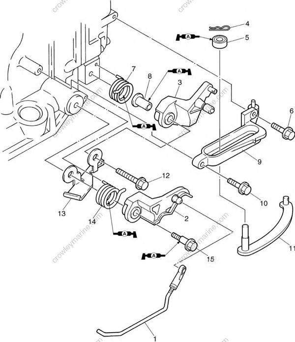
| No. | Part name | Q’ty | Remarks | Tightening torques | Tightening torques | Tightening torques | Tightening torques |
|---|---|---|---|---|---|---|---|
| Stage | N⋅m | kgf⋅m | ft⋅lb | ||||
| 1 | Throttle link rod | 1 | |||||
| 2 | Throttle cam | 1 | |||||
| 3 | Throttle control lever | 1 | |||||
| 4 | Clip | 1 | |||||
| 5 | Bushing | 1 | |||||
| 6 | Bolt | 1 | M6 x 20 mm | ||||
| 7 | Spring | 1 | |||||
| 8 | Collar | 1 | |||||
| 9 | Bracket | 1 | |||||
| 10 | Bolt | 1 | M6 x 30 mm | ||||
| 11 | Shift rod | 1 | |||||
| 12 | Bolt | 1 | M6 x 30 mm | ||||
| 13 | Bracket | 1 | |||||
| 14 | Spring | 1 | |||||
| 15 | Bolt | 1 |
Checking the compression pressure
Start the engine, warm it up for 5 minutes, and then turn it off.
Remove the clip from the engine stop lanyard switch on the remote control box or tiller handle.
Remove the all spark plugs, and then install the special service tool to each spark plug hole.
Before removing the spark plugs, blow compressed air in the spark plug well to clear out any dirt or dust that may fall into the cylinder.
Compression gauge (T): YU-33223-1 / 90890-03160
- Fully open the throttle, crank the engine until the reading on the compression gauge stabilizes, and then check the compression pressure.
Minimum compression pressure: (reference data) 840 kPa (8.4 kgf/cm2, 122 psi)
- If the compression pressure is below specification and the compression pres sure for each cylinder is unbalanced, add a small amount of engine oil to the cylinder, and then check the pressure again. 5-25
• If the compression pressure increases, check the piston and piston rings for wear. Replace if necessary.
• If the compression pressure does not increase, check the valve clearance, valve, valve seat, cylinder sleeve, cylinder head gasket, and cylinder head. Adjust or replace if necessary.
Checking the oil pressure
Start the engine, warm it up for 5 minutes, and then turn it off.
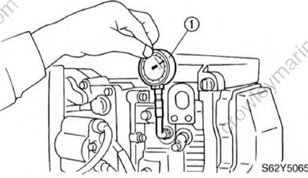
Remove the oil pressure switch, and then install an oil pressure gauge (1) to the oil pressure switch installation hole.
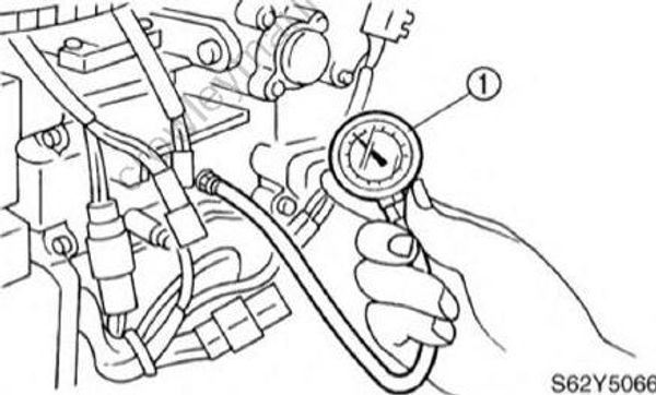
Use a pressure gauge with an adapter with a 1/8 pitch thread.
- Check the oil pressure. Check the oil pump, oil suction pipe, and oil strainer if out of specification.
Oil pressure: (reference data) : 100 kPa (1.0 kgf/cm2, 14 psi) at idle speed
Removing the power unit
- Remove the flywheel magnet cover and flywheel magnet.
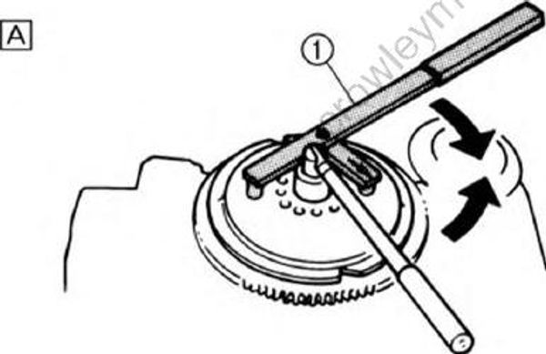
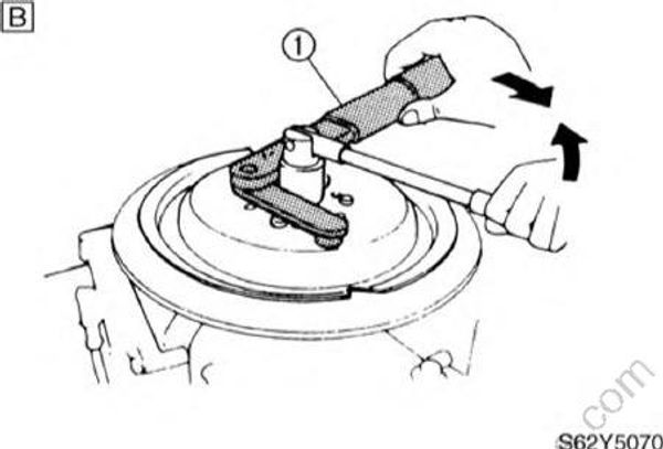
[A] For USA and Canada
[B] For worldwide
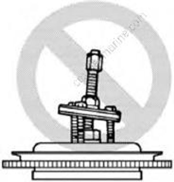
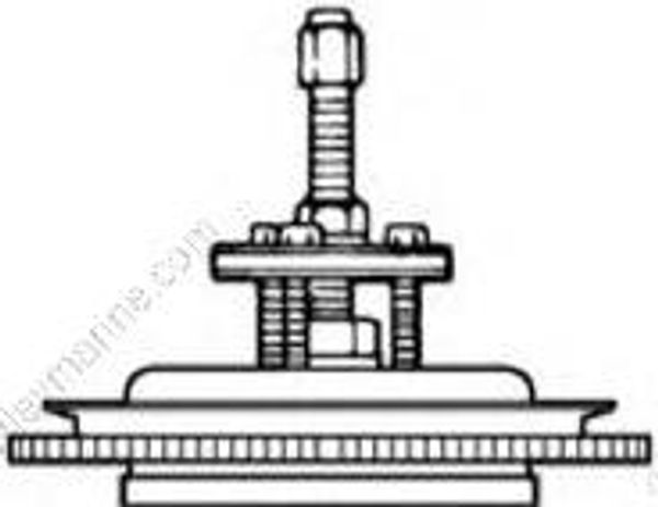
• Apply force in the direction of the arrows shown, to prevent the flywheel holder from slipping off easily.
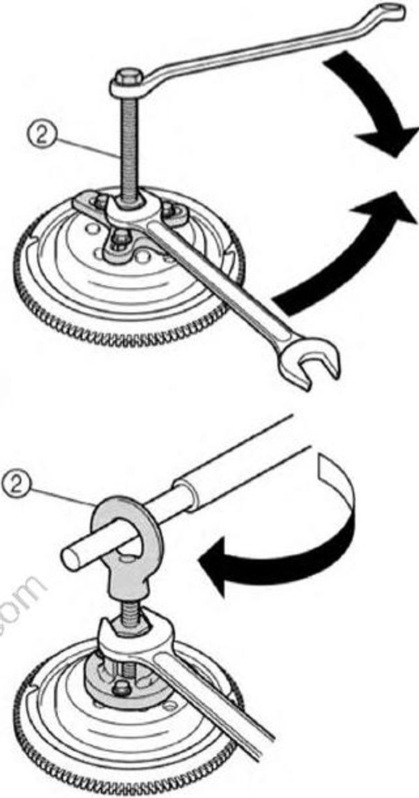
• To prevent damage to the engine or tools, screw in the flywheel puller set bolts evenly and completely so that the flywheel puller plate is parallel to the fly wheel magnet.
Apply force to the crankshaft end until the fly wheel magnet comes off the tapered portion of the crankshaft.
Flywheel magnet holder(1): YB-06139
Flywheel holder (1): 90890-06522
Universal puller (2): YB-06117
Flywheel puller (2): 90890-06521
- Disconnect the throttle cable (1) and shift cable/shift rod (2).
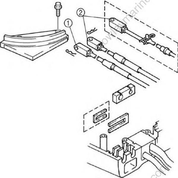
- Disconnect the fuel hose (3) and throttle link rod (4).
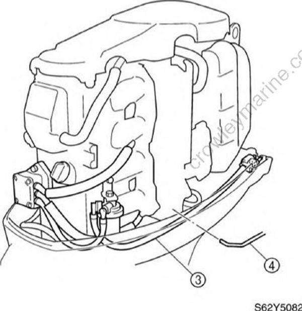
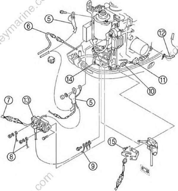
Disconnect the battery leads (5), 10-pin coupler(6), PTT relay leads (7) (EHT, ET), PTT motor leads (8)(EHT, ET), ground lead (9) (EHT, ET), warning indicator coupler (10) (EHD, EHT), trailer switch coupler (11) (EHT, ET), trim sensor coupler (TR), pilot water hose (12), and flushing hose (models with flushing device).
Remove the power trim and tilt relay (13), shift rod (14) and shift rod bolts (15).
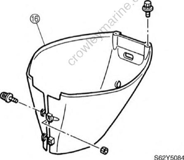
- Remove the apron (16).
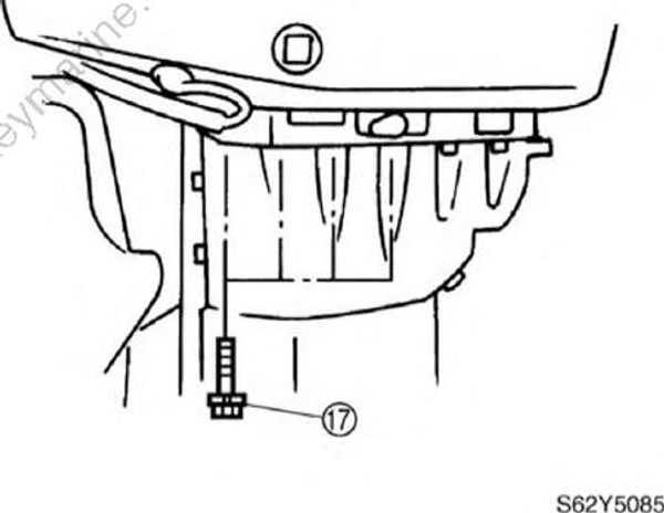
- Remove the power unit by removing the bolts (17).