

EXPLODED DIAGRAM
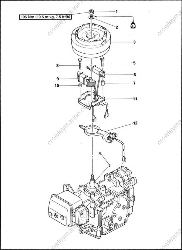
REMOVAL AND INSTALLATION CHART
| Step | Procedure/Part name | Q’ty | Service points |
|---|---|---|---|
| FLYWHEEL MAGNETO AND MAGNETO BASE REMOVAL | Follow the left "Step" for removal. | ||
| Recoil starter assembly | Refer to the "RECOIL STARTER" section. | ||
| 1 | Nut | 1 | |
| 2 | Plane washer | 1 | |
| 3 | Flywhee | 1 | |
| 4 | Woodruff key | 1 | |
| 5 | Bolt (with washer) | 2 | |
| 6 | Charge coil | 1 | |
| 7 | Collar | 2 | |
| 8 | Bolt (with washer) | 2 | |
| 9 | Lighting coil | 1 | |
| 10 | Collar | 2 | |
| 11 | Magneto base plate | 1 | |
| 12 | Pulser coil assembly | 1 | |
| Reverse the removal steps for installation. |
Service points
Flywheel magneto removal
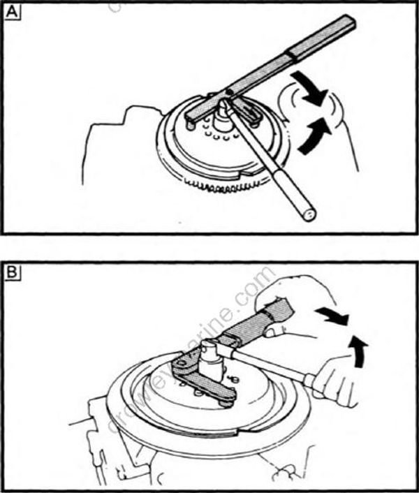
- Remove and install:
• Flywheel nut
Flywheel holder:
YB-06139/90890-06522
[A] For USA and CANADA
[B] Except for USA and CANADA
CAUTION: The major load should be carried in the direction of the arrows. If not, the holder may easily slip off.

- Remove:
• Flywheel magneto
Flywheel puller: YB-06117/90890-06521
[A] For USA and CANADA
[B] Except for USA and CANADA
CAUTION:
• Keep the nut side flush with the crankshaft end until the flywheel comes off the
tapered portion of the crankshaft.
• To prevent damage to the engine or tools,screw in the flywheel magneto- puller set bolts evenly and completely so thatthe puller plate is parallel to the flywheel
