

EXPLODED DIAGRAM
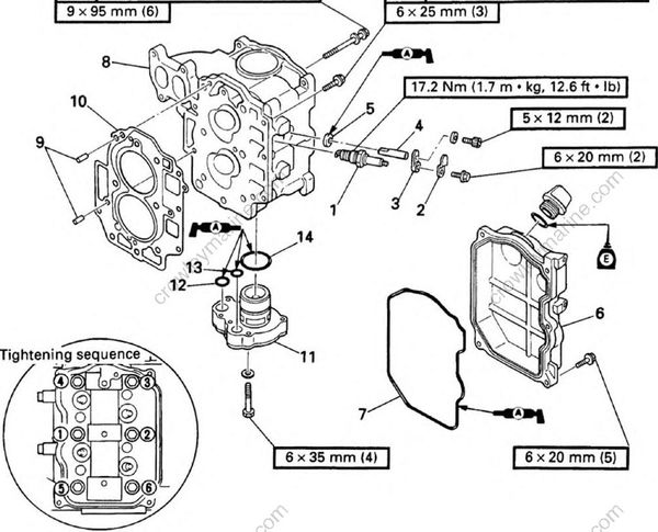
REMOVAL AND INSTALLATION CHART
| Step | Procedure/Part name | Q'ty | Service points |
|---|---|---|---|
| CYLINDER HEAD AND OIL PUMP REMOVAL | Follow the left "Step" for removal. | ||
| 1 | Spark plug | 2 | |
| 2 | Plate | 2 | |
| 3 | Anode cover | 2 | |
| 4 | Anode | 2 | |
| 5 | Grommet | 2 | |
| 6 | Cylinder head cover | 1 | |
| 7 | Rubber gasket | 1 | |
| 8 | Cylinder head | 1 | |
| 9 | Dowel pin | 2 | |
| 10 | Gasket | 1 | Not reusable |
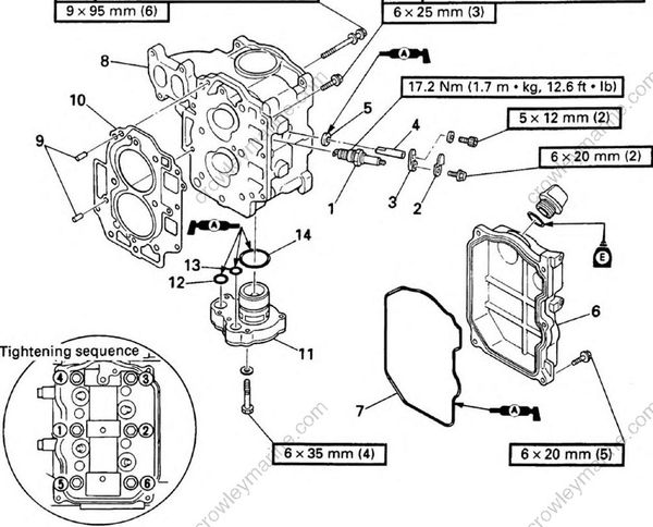
| Step | Procedure/Part name | Q'ty | Service points |
|---|---|---|---|
| 11 | Oil pump | 1 | |
| 12 | O-ring | 1 | 33.0 x 1.9 mm |
| 13 | O-ring | 1 | 13.5 x 1.8 mm |
| 14 | O-ring | 1 | 11.5 x 1.2 mm |
| Reverse the removal steps for installation. |
