

Cylinder body
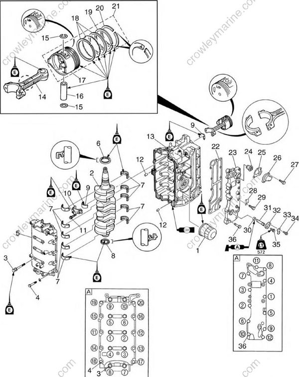
S62Y5685
| No. | Part name | Q’ty | Remarks | Tightening torques | Tightening torques | Tightening torques | Tightening torques |
|---|---|---|---|---|---|---|---|
| Stage | N⋅m | kgf⋅m | ft⋅lb | ||||
| 1 | Oil filter | 1 | 18 | 1.8 | 13 | ||
| 2 | Crankshaft | 1 | |||||
| 3 | Bolt | 10 | M8 x 82 mm | 1st | 15 | 1.5 | 11 |
| 3 | Bolt | 10 | M8 x 82 mm | 2nd | 30 | 3.0 | 22 |
| 4 | Bolt | 10 | M6 x 35 mm | 1st | 6 | 0.6 | 4.3 |
| 4 | Bolt | 10 | M6 x 35 mm | 2nd | 12 | 1.2 | 8.7 |
| 5 | Crankcase | 1 | |||||
| 6 | Oil seal | 1 | Not reusable | ||||
| 7 | Main bearing | 10 | |||||
| 8 | Oil seal | 1 | Not reusable | ||||
| 9 | Connecting rod bearing | 8 | |||||
| 10 | Connecting rod cap | 4 | |||||
| 11 | Bolt | 8 | 1st | 6 | 0.6 | 4.3 | |
| 11 | Bolt | 8 | 2nd | 17 | 1.7 | 12 | |
| 12 | Dowel pin | 2 | |||||
| 13 | Cylinder body | 1 | |||||
| 14 | Connecting rod | 1 | |||||
| 15 | Piston pin clip | 2 | Not reusable | ||||
| 16 | Piston pin | 1 | |||||
| 17 | Piston | 1 | |||||
| 18 | Oil ring | 1 | |||||
| 19 | Second ring | 1 | |||||
| 20 | Top ring | 1 | |||||
| 21 | Piston assembly | 1 | |||||
| 22 | Gasket | 1 | Not reusable | ||||
| 23 | Exhaust cover | 1 | |||||
| 24 | Thermostat | 1 | |||||
| 25 | Gasket | 1 | Not reusable | ||||
| 26 | Cover | 1 | |||||
| 27 | Bolt | 2 | M6 x 35 mm | ||||
| 28 | Clamp | 1 | |||||
| 29 | Bolt | 10 | |||||
| 30 | Grommet | 1 |
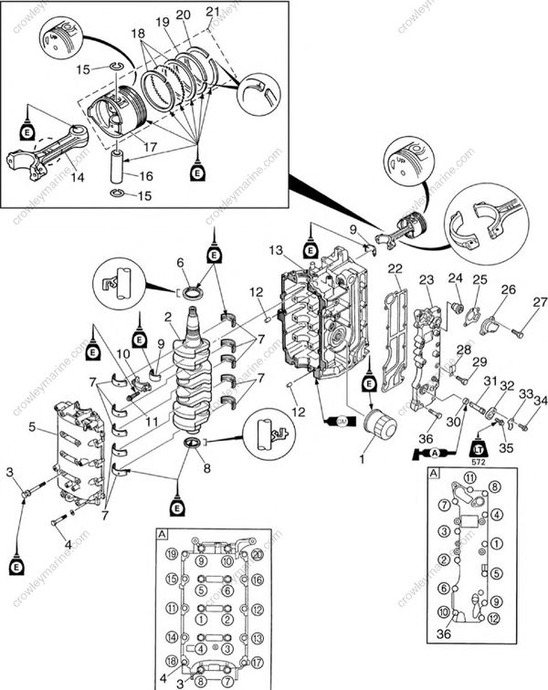
S62Y5685
| No. | Part name | Q’ty | Remarks | Tightening torques | Tightening torques | Tightening torques | Tightening torques |
|---|---|---|---|---|---|---|---|
| Stage | N⋅m | kgf⋅m | ft⋅lb | ||||
| 31 | Anode | 1 | |||||
| 32 | Cover | 1 | |||||
| 33 | Cover | 1 | |||||
| 34 | Bolt | 1 | M6 x 20 mm | ||||
| 35 | Bolt | 1 | M5 x 12 mm | ||||
| 36 | Bolt | 10 | M6 x 35 mm | 1st | 6 | 0.6 | 4.3 |
| 36 | Bolt | 10 | M6 x 35 mm | 2nd | 12 | 1.2 | 8.7 |
[A] Tightening sequence
Removing and installing the oil filter
- Place a rag under the oil filter, and then remove the filter.
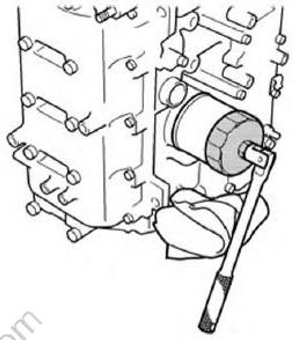
S62Y5690
Oil filter wrench: YU-38411 / 90890-01426
Be sure to clean up any oil spills.
Apply a thin coat of the new engine oil to the O-ring of the new oil filter.
Install the oil filter, and then tighten it to the specified torque.
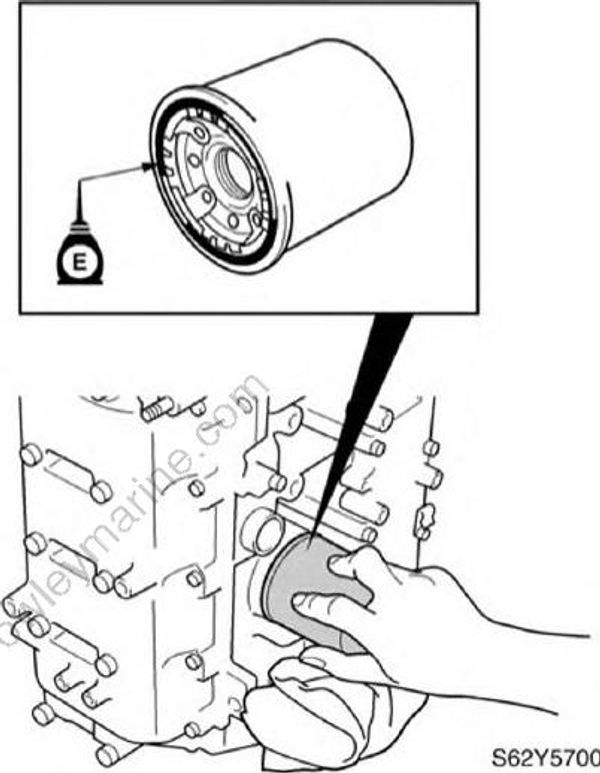
S62Y5700
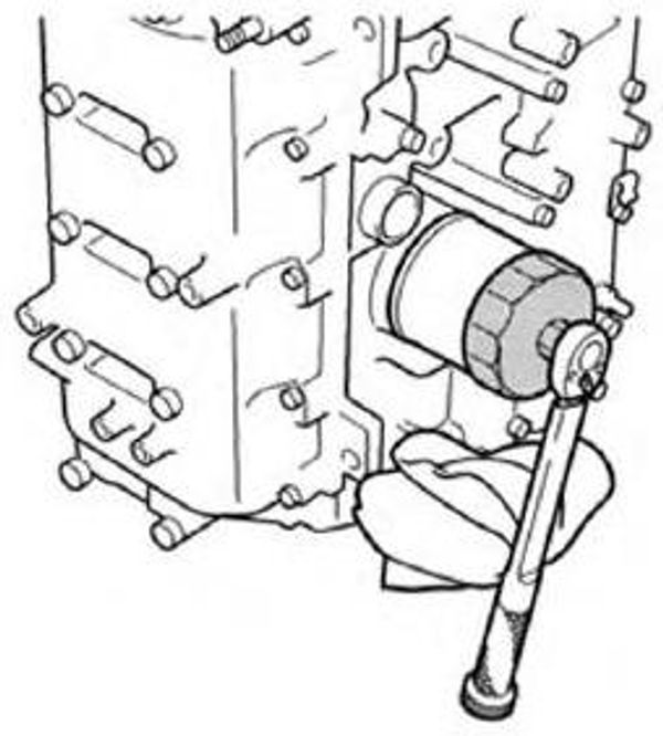
S62Y5710
Oil filter wrench: YU-38411 / 90890-01426
Oil filter: 18 N⋅m (1.8 kgf⋅m, 13 ft⋅lb)
Disassembling the cylinder body
- Remove the exhaust cover bolts in the sequence shown.
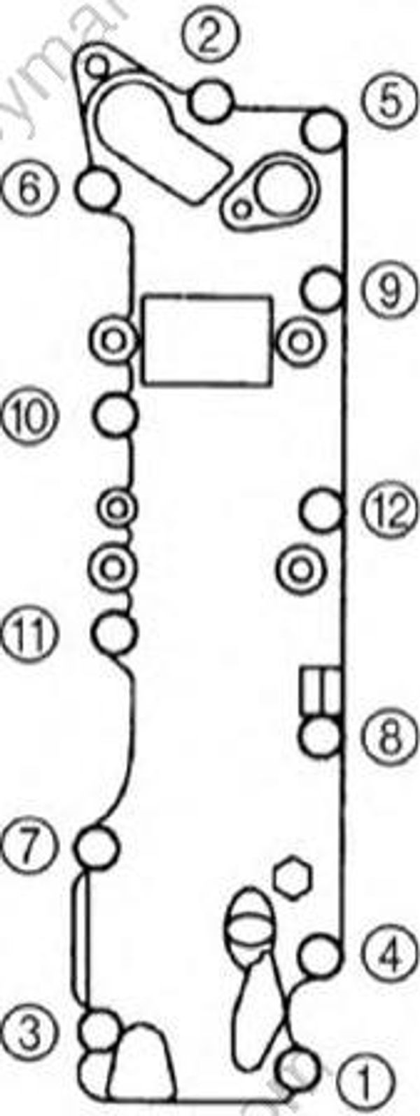
S62Y5720
- Remove the crankcase bolts in the sequence shown.
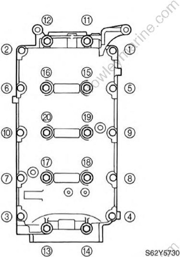
S62Y5730
Remove the connecting rod bolts and the piston assemblies.
Remove the crankshaft, oil seals, and dowel pins.
Remove the piston pin clip (1) with pliers, and then remove the piston.
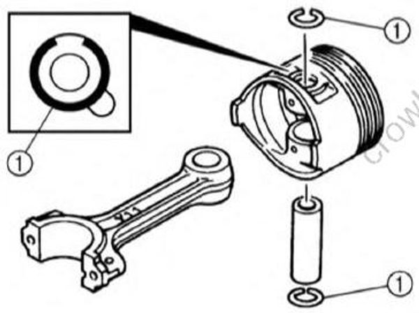
S62Y5740
Checking the piston diameter
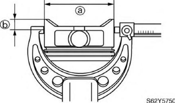
- Measure the piston outside diameter at the specified measuring point. Replace if out of specification.
S62Y5750
Piston diameter: 62.95 - 62.96 mm (2.4783 - 2.4787 in)
Measuring point(b): 5 mm (0.2 in) up from the bottom of the piston skirt
Oversize piston diameter:
Oversize 1: +0.25 mm (0.0098 in)
Oversize 2: +0.50 mm (0.0196 in)
Checking the cylinder bore
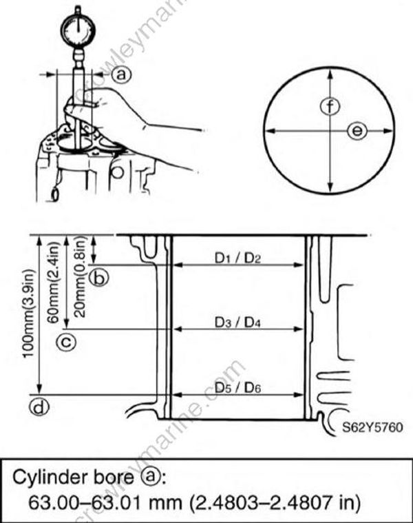
- Measure the cylinder bore (D1-D6) (a) at measuring points (B),(C) and (D), and in direction (e), which is parallel to the crankshaft, and direction (f), which is at a right angle to the crankshaft.
S62Y5768
Cylinder bore (a): 63.00-63.01 mm (2.4803-2.4807)
- Calculate the taper limit. Replace or rebore the cylinder body if out of specification.
Taper limit = maximum of D1 or D2 minimum of D5 or D6: 0.08 mm (0.0031 in)
- Calculate the out-of-round limit. Replace or rebore the cylinder body if out of specification.
Out-of-round limit = maximum of D,, D3, or D5 minimum of D2, D4, or D6: 0.05 mm (0.0020 in)
Checking the piston clearance
- Rebore the cylinder or replace the piston and piston rings as a set or the cylinder body, or both if out of specification.
Piston clearance: 0.035-0.065 mm (0.0014-0.0025 in)
Checking the piston rings
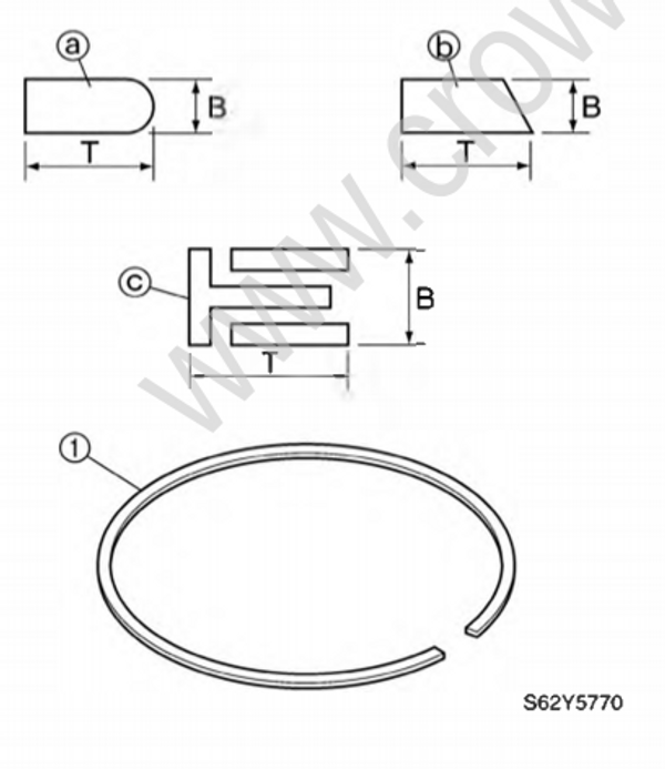
- Check the piston ring (1) dimensions of B and T. Replace if out of specification.
S62Y5770
Piston ring dimensions:
Top ring (a):
B: 1.17-1.19 mm (0.0461-0.0468 in)
T: 2.30-2.50 mm (0.0906-0.0984 in)
Second ring (b):
B: 1.47-1.49 mm (0.0579-0.0586 in)
T: 2.40-2.60 mm (0.0945-0.1024 in)
Oil ring (c):
B: 2.34-2.46 mm (0.0921-0.0969 in)
T: 2.75 mm (0.1083 in)
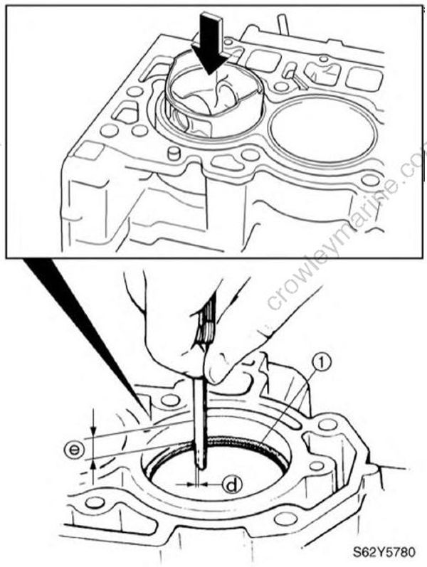
Level the piston ring (1) in the cylinder with the piston crown of an inverted piston.
Check the piston ring end gap (d) at the specified measuring point. Replace if out of specification.
S62Y5780
Piston ring end gap (d):
Top ring: 0.15 - 0.30 mm (0.0060 - 0.0118 in)
Second ring: 0.30 - 0.50 mm (0.0118 - 0.0196 in)
Oil ring: 0.20 - 0.70 mm (0.0079 - 0.0275 in)
Measuring point (e): 20 mm (0.8 in)
Checking the piston ring grooves
- Measure the piston ring grooves. Replace the piston if out of specification.
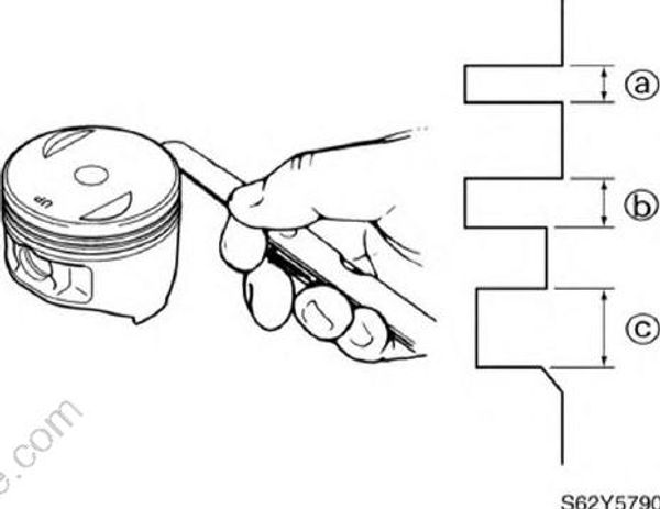
S62Y5790
Piston ring groove(a):
Top ring (a): 1.23 - 1.25 mm (0.048 - 0.049 in)
Second ring (b): 1.52 - 1.54 mm (0.060 - 0.061 in)
Oil ring (c): 2.51 - 2.53 mm (0.099 - 0.100 in)
Checking the piston ring side clearance
- Measure the piston ring side clearance. Replace the piston and piston rings as a set if out of specification.
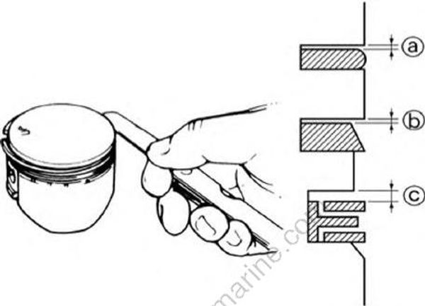
S62Y5800
Piston ring side clearance:
Top ring (a): 0.04 - 0.08 mm (0.0016 - 0.0032 in)
Second ring (b): 0.03 - 0.07 mm (0.0012 - 0.0028 in)
Oil ring (c): 0.05 - 0.19 mm (0.0020 - 0.0075 in)
Checking the piston pin boss bore
- Measure the piston pin boss bore. Replace the piston if out of specification.
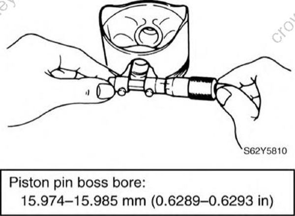
S62Y5810
Piston pin boss bore: 15.974 - 15.985 mm (0.6289 - 0.6293 in)
Checking the piston pin
- Measure the piston pin diameter. Replace if out of specification.
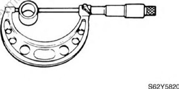
S62Y5820
Piston pin diameter: 15.965 - 15.970 mm (0.6285 - 0.6287 in)
Checking the connecting rod small end inside diameter
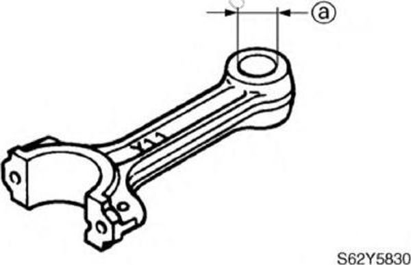
- Measure the connecting rod small end inside diameter (a). Replace the connecting rod if out of specification.
S62Y5830
Connecting rod small end inside diameter (a): 15.985 - 15.998 mm (0.6293 - 0.6298 in)
Checking the connecting rod big end side clearance
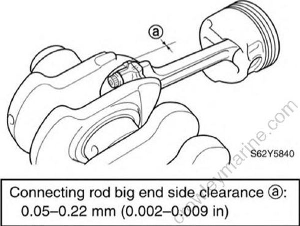
- Measure the connecting rod big end side clearance (a). Replace the connecting rod or crankshaft, or both if out of specification.
S62Y5840
Connecting rod big end side clearance (a): 0.05 - 0.22 mm (0.002 - 0.009 in)
Checking the connecting rod bolt
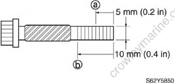
Measure the connecting rod bolt thread diameter at the two points (a) and (b).
Calculate the difference between (a) and (b) Replace if out of specification.
S62Y5850
Connecting rod bolt thread diameter limit (difference between (a) and (b)): 0 - 0.1 mm (0 - 0.004 in)
Checking the crankshaft
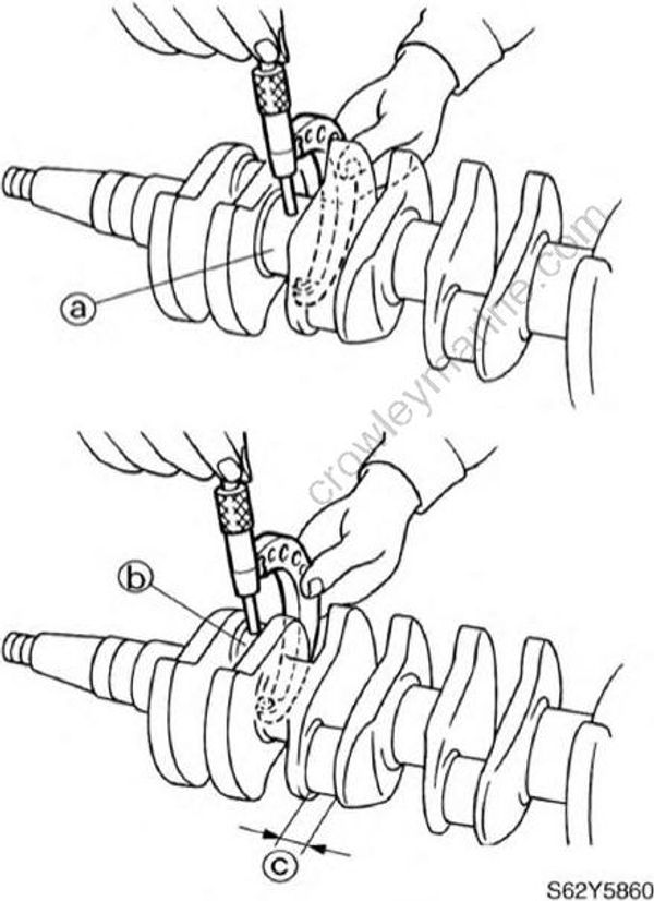
- Measure the crankshaft journal diameter (a), crank pin diameter (b), and crank pin width (c). Replace the crankshaft if out of specification.
S62Y5860
Crankshaft journal diameter(a): 42.984 - 43.000 mm (1.6923 - 1.6929 in)
Crank pin diameter(b): 32.984 - 33.000 mm (1.2986 - 1.2992 in)
Crank pin width (c): 21.000 - 21.070 mm (0.8268 - 0.8295 in)
- Measure the crankshaft runout. Replace the crankshaft if out of specification.
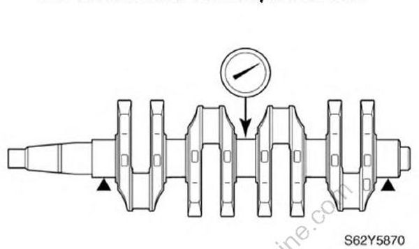
S62Y5870
Crankshaft runout limit: 0.03 mm (0.0012 in)
Checking the crankshaft main journal oil clearance
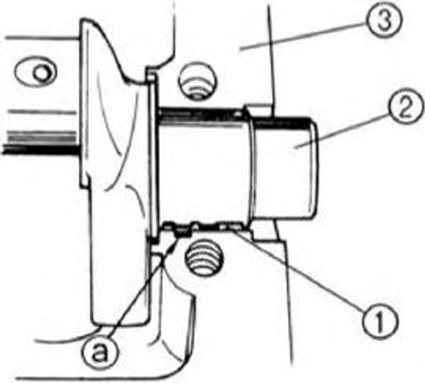
Clean the bearings, main journals, and bearing portions of the crankcase and cylinder body.
Place the cylinder body upside down on a bench.
Install half of the bearings (1) and the crankshaft (2) into the cylinder body (3).
S62Y5910
Install the bearings in their original positions.
Insert the projection (a) of the bearing into the notch in the cylinder body.
- Put a piece of Plastigauge (R) (PG-1) on each main journal parallel to the crank shaft.
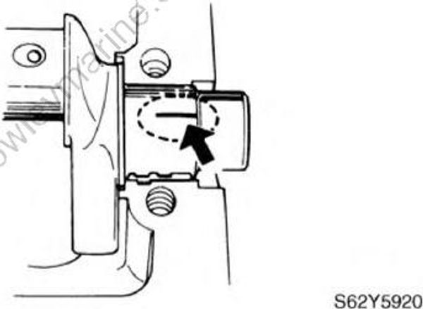
S62Y5920
Do not put the Plastigauge (PG-1) over the oil hole in the main journals of the crankshaft.
- Install the remaining half of the bearings into the crankcase.
Insert the projection of the bearing into the notch in the crankcase.
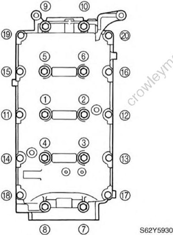
Install the crankcase onto the cylinder body and apply engine oil onto the threads of the crankcase bolts.
Tighten the crankcase bolts to the specified torques in two stages and in the sequence shown.
S62Y5930
Do not move the crankshaft until the main journal oil clearance measurement has been completed.
Crankcase bolt (M8):
1 st: 15 N⋅m (1.5 kgf⋅m, 11 ft⋅1b)
2nd: 30 N⋅m (3.0 kgf⋅m, 22 ft-lb)
Crankcase bolt (M6):
1st: 6 N⋅m (0.6 kgf⋅m, 4.3 ft⋅lb)
2nd: 12 N⋅m (1.2 kgf⋅m, 8.7 ft⋅lb)
- Remove the crankcase and measure the width of the compressed Plastigauge (PG-1) on each main journal. Replace the main bearing if out of specification.
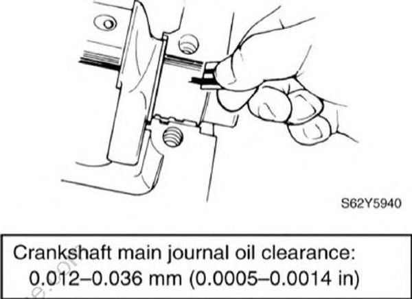
S62Y5940
Crankshaft main journal oil clearance: 0.012 - 0.036 mm (0.0005 - 0.0014 in)
Checking the crankshaft pin oil clearance
Clean the bearings and the connecting rod.
Install the upper half of the bearing into the connecting rod (1) and the lower half into the connecting rod cap (2).
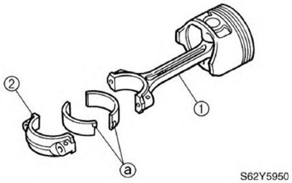
S62Y5950
Install the bearings in their original positions.
Insert the projection (a) of the bearing into the slot on the cap and connecting rod.
- Put a piece of Plastigauge (PG-1) onto the crank pin, parallel to the crankshaft.
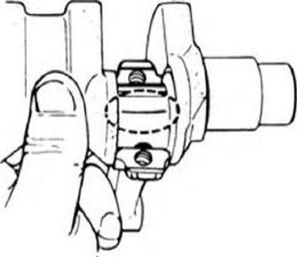
S62Y5960
Be sure not to put the Plastigauge (PG-1) over the oil hole in the crank pin of the crank shaft.
- Install the connecting rod to the crank pin
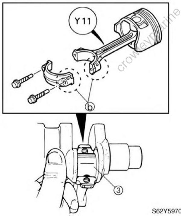
S62Y5970
• Align the alignment marks (b) on the connecting rod cap and connecting rod.
• Face the embossed “Y” mark on the connecting rod toward the flywheel side of the crankshaft.
- Tighten the connecting rod bolts to the specified torques in two stages.
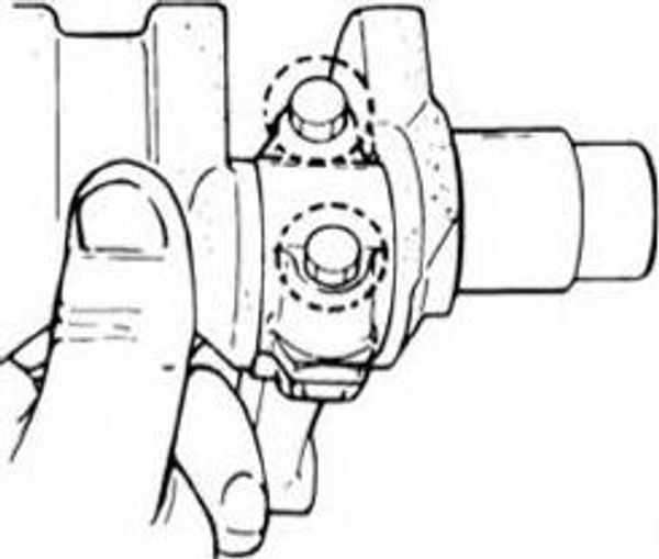
S62Y5980
Do not turn the connecting rod until the crank pin oil clearance measurement has been completed.
Connecting rod bolt:
1st: 6 N⋅m (0.6 kgf⋅m, 4.3 ft⋅lb)
2nd: 17 N⋅m (1.7 kgf⋅m, 12 ft⋅lb)
- Remove the connecting rod cap and measure the width of the compressed Plastigauge (PG-1) on each crank pin. Replace the connecting rod bearing if out of specification.
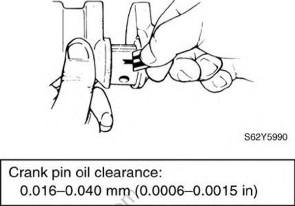
S62Y5990
Crank pin oil clearance: 0.016- 0.014 ( 0.0006-0.00015 in)
Selecting the crankshaft main journal bearing
When replacing the main bearing, select the suitable bearing as follows.
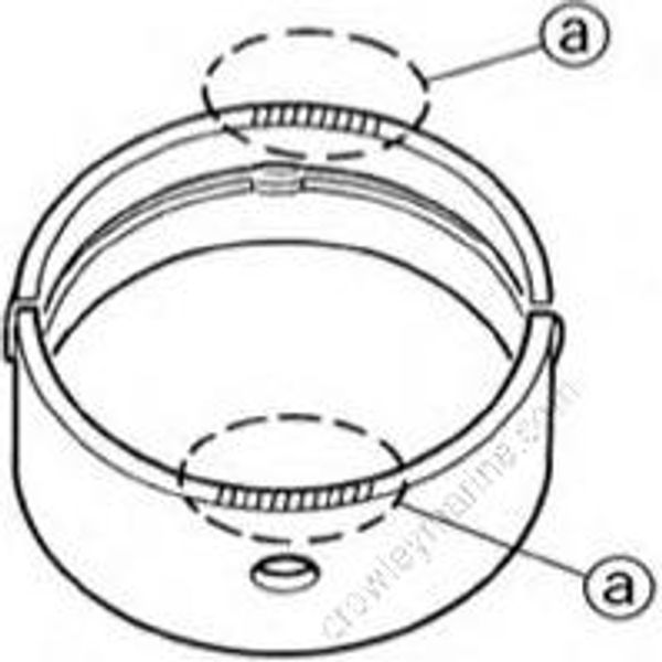
Check the crankshaft journal mark on the crankshaft (1) and the cylinder body mark on the cylinder body (2).
Select the suitable color (a) for the main bearing from the table.
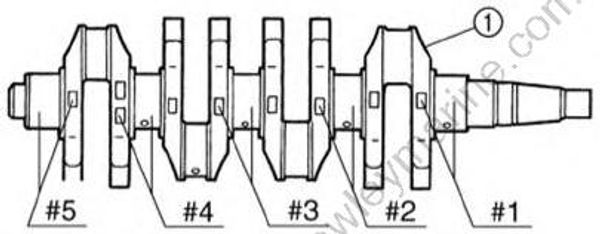
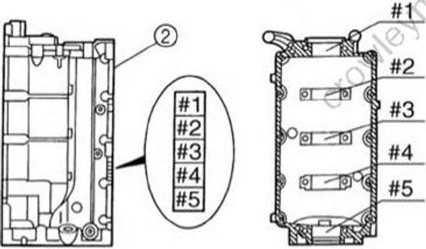
S62Y5A10
| Cylinder body mark | Crankshaft journal mark | Bearing color |
|---|---|---|
| A | A | Yellow |
| A | B | Red |
| B | A | Red |
| B | B | Pink |
| C | A | Pink |
| C | B | Green |
- When installing the main bearing, insert the projection of the main bearing into the slot on the cylinder body.
Remove any small metal particles and oil from the contact surfaces of the cylinder body and the main bearing.
- Measure the main journal oil clearance with a piece of Plastigauge (PG-1).
Crankshaft main journal oil clearance: 0.012 - 0.036 mm (0.0005 - 0.0014 in)
If the oil clearance is below specification, check the main bearing color and clean the contact surface of the cylinder body and the main bearing, and then check the main journal oil clearance again.
If the oil clearance is over specification, install an oversized main bearing, and then check the main journal oil clearance again.
Selecting the connecting rod big end bearing
When replacing the connecting rod bearing, select the suitable connecting rod bearing as follows.
Check the crank pin mark on the crank shaft (1) and the connecting rod cap mark or painted color on the connecting rod (2).
Select the suitable color (a) for the connecting rod bearing from the table.

S62Y5A20
| Connecting rod cap mark/color | Crank pin mark | Bearing color |
|---|---|---|
| I/Red | A | Yellow |
| l/Red | B | Red |
| II/Blue | A | Red |
| II/Blue | B | Pink |
| III/Yellow | A | Pink |
| III/Yellow | B | Green |
- When installing the connecting rod bearing, insert the projection of the connecting rod bearing into the slot on the connecting rod.
Remove any small metal particles and oil from the contact surfaces of the connecting rod and the connecting rod bearing.
- Measure the crank pin oil clearance with a piece of Plastigauge (PG-1).
Crank pin oil clearance: 0.016 - 0.040 mm (0.0006 - 0.0015 in)
If the oil clearance is below specification, check the connecting rod bearing color and clean the contact surface of the connecting rod and the connecting rod bearing, and then check the crank pin oil clearance again.
If the oil clearance is over specification, install an over-sized connecting rod bearing, and then check the crank pin oil clearance again.
Assembling the cylinder body
- Assemble the piston (1), connecting rod (2) , piston pin (3), and piston pin clips(4).
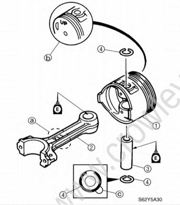
S62Y5A30
• Face the embossed “Y” mark (a) on the connecting rod in the same direction as the “UP” mark (b) on the piston.
• Always use new piston pin clips, and do not allow the piston pin clip end to align with the piston pin slot (c).
Install the oil ring (5), second ring (6), and top ring (7) to the piston with the “T” mark (T) on the piston rings facing upward.
Offset the piston ring end gaps as shown.
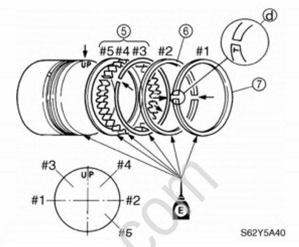
S62Y5A40
Do not scratch the piston or break the piston rings.
After installing the piston rings, check that they move smoothly.
- Install the upper half of the bearing into the connecting rod (2) and the lower half into the connecting rod cap (8).
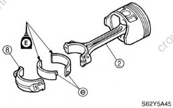
S62Y5A45
Install the bearings in their original position.
Insert the projection (e) of the bearing into the slot on the cap and connecting rod.
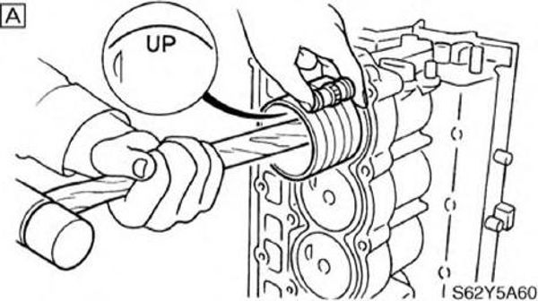
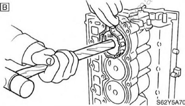
- Install the piston with the “UP” mark on the piston crown facing towards the fly wheel.
S62Y5A60
S62Y5A70
[A] For USA and Canada
[B] For worldwide
Apply engine oil to side of the piston assembly
Piston ring compressor: YU-33294
Piston slider: 90890-06529
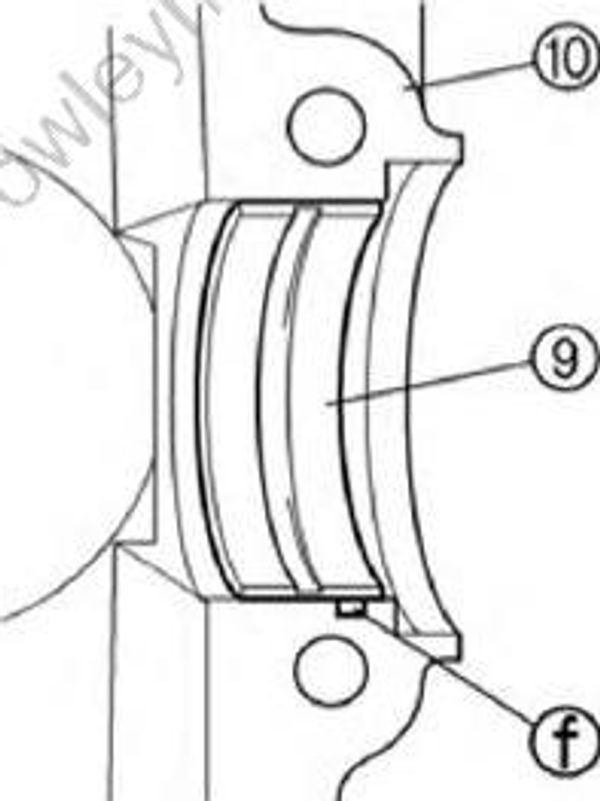
- Install half of the bearings (9) into the cylinder body(10).
S62Y5A81
Insert the projection (f) of the bearing into the notch in the cylinder body.
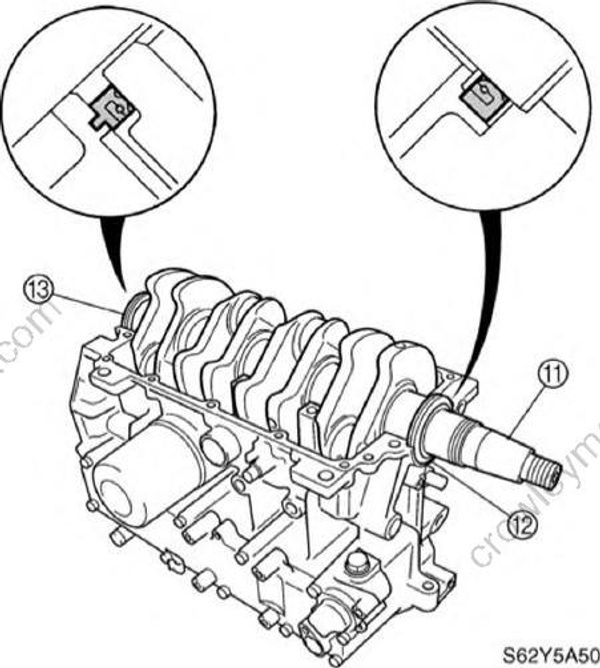
- Set the crankshaft (11) and oil seals (12) and (13) into the cylinder body as shown. Apply engine oil to the inner oil seal, journal bearings, and connecting rod bearing.
S62Y5A50
- Install the connecting rod cap (8) to the connecting rod, and then tighten the connecting rod bolts (14) to the specified torques in two stages. Apply engine oil to the connecting rod cap and connecting rod bolt.
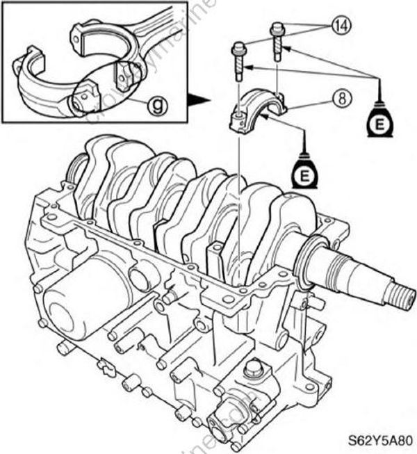
S62Y5A80
Align the alignment marks (g) on the connecting rod cap and connecting rod.
Connecting rod bolt:
1st: 6 N⋅m (0.6 kgf⋅m, 4.3 ft⋅lb)
2nd: 17 N⋅m (1.7 kgf⋅ m, 12 ft⋅lb)
Install half of the bearings (g) into the crankcase, then dowel pins (15).
Apply Gasket Maker (R) to the mating surface of the crankcase.
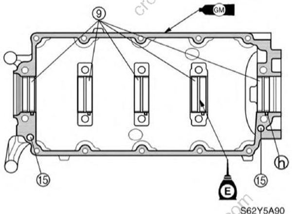
S62Y5A90
• Insert the projection (h) of the bearing into the notch in the crankcase.
• Do not get any Gasket Maker on the journal bearings.
- Install the crankcase bolts, and then tighten them to the specified torques in two stages and in the sequence shown.
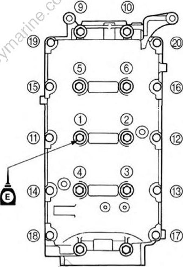
S62Y5B10
The oil seals must be installed before tightening the crankcase bolts.
Apply engine oil to the crankcase bolt (M8) before installation.
Crankcase bolt (M8):
1st: 15 N⋅m (1.5 kgf⋅m, 11 ft⋅lb)
2nd: 30 N⋅m (3.0 kgf⋅m, 22 ft⋅lb)
Crankcase bolt (M6):
1st: 6 N⋅m (0.6 kgf⋅m, 4.3 ft⋅lb)
2nd: 12 N⋅m (1.2 kgf⋅m, 8.7 ft⋅lb)
- Install the new gasket and exhaust cover, and then tighten the bolts to the specified torques in two stages and in the sequence shown.
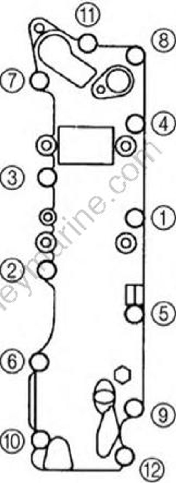
S62Y5B20
Exhaust cover bolt:
1st: 6 N⋅m (0.6 kgf⋅m, 4.3 ft⋅lb)
2nd: 12 N⋅m (1.2 kgf⋅m, 8.7 ft⋅lb)
Installing the power unit
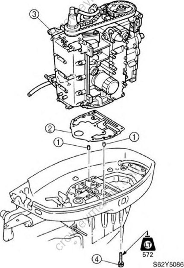
Install the dowel pins (1) and gasket (2).
Install the power unit (3) by installing the bolts (4), then tightening them to the specified torque.
S62Y5086
Mounting bolt (4): 21 N⋅m (2.1 kgf⋅m, 15 ft⋅lb)
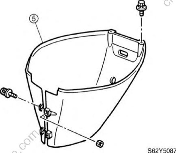
- Install the apron (5).
S62Y5087
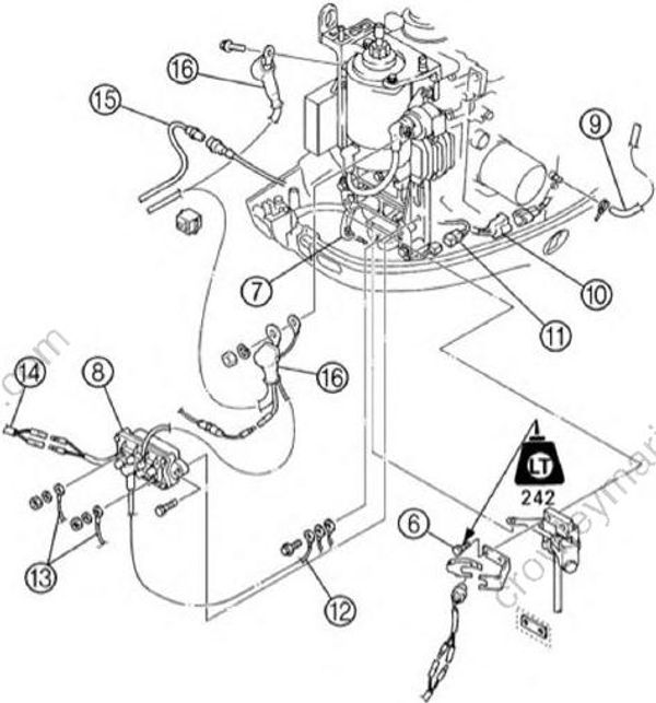
Install the shift rod bolts (6), shift rod (7) and power trim and tilt relay (8).
Connect the flushing hose (models with flushing device), pilot water hose (9), trim sensor coupler (TR), trailer switch coupler (10) (EHT, ET), warning indicator coupler (11) (EHD, EHT), ground lead (12) (EHT, ET), PTT motor leads (13) (EHT, ET), PTT relay leads (14) (EHT, ET), 10 pin coupler (15), and battery leads(16).
S62Y5088
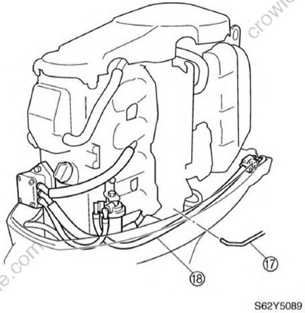
- Connect the throttle link rod (17) and fuel hose (18).
S62Y5089
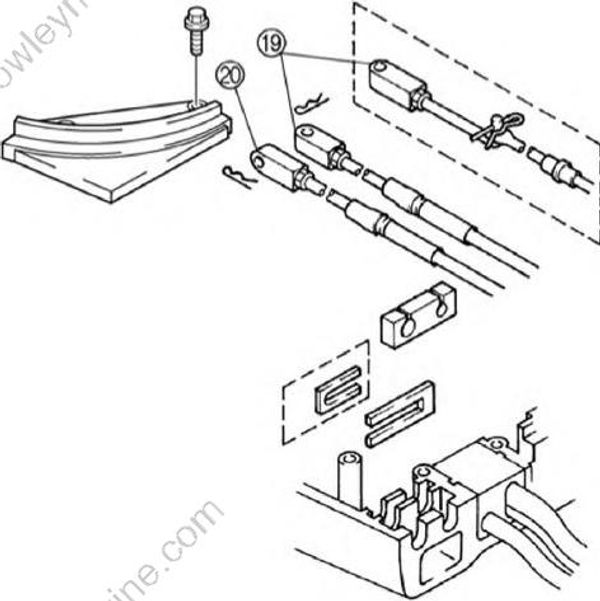
- Connect the shift cable/shift rod (19) and throttle cable (20), and then adjust their lengths. For adjustment procedures, see Chapter 3, “Checking the throttle cable operation,” and “Checking the gearshift operation.”
S62Y5091R
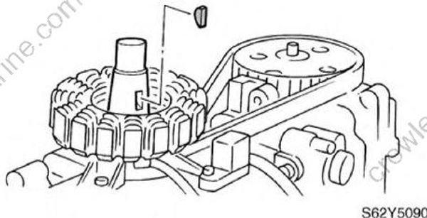
- Install the Woodruff key.
S62Y5090
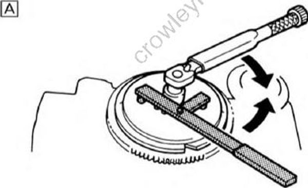
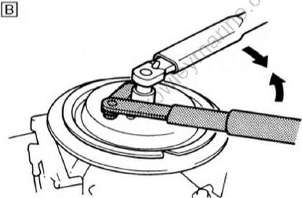
- Install the flywheel magnet and flywheel magnet cover.
S62Y5100
[A] For USA and Canada
[B] For worldwide
Apply force in the direction of the arrows shown, to prevent the flywheel holder from slipping off easily.
Apply engine oil to the flywheel magnet nut before installation.
Flywheel magnet holder: YB-06139
Flywheel holder: 90890-06522
Flywheel magnet nut: 160 Nm (16 kgf⋅m, 116 ft⋅lb)
