

EXPLODED DIAGRAM
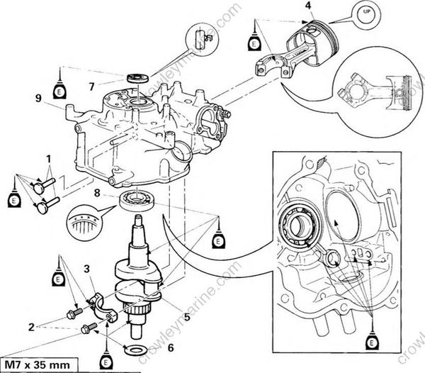
REMOVAL AND INSTALLATION CHART
| Step | Procedure/Part name | Q'ty | Service points |
|---|---|---|---|
| CRANKSHAFT AND CYLINDER BODY REMOVAL | Follow the left "Step" for removal. | ||
| 1 | Valve lifter | 2 | |
| 2 | Bolt (connecting rod cap) | 2 | |
| 3 | Connecting rod cap | 1 | |
| 4 | Connecting rod and piston ass'y | 1 | |
| Install the connecting rod and piston ass'y "YAMAHA" mark side to the rotor side. |
|||
| 5 | Crankshaft | 1 | |
| 6 | Plate washer | 1 | |
| 7 | Oil seal (cylinder body) | 1 | Not reusable |
| 8 | Ball bearing | 1 | |
| 9 | Cylinder body | 1 | |
| Reverse the removal steps for installation. |
