Cylinder head
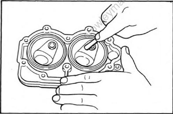
Using a rounded scraper, remove any carbon deposits from combustion chamber. Take care to avoid damaging the spark plug threads. Do not use a sharp instrument. Avoid scratching the aluminum.
Thoroughly clean the cylinder head water jacket of salt and dirt. Patch up any part from which anti-corrosion paint has come off. Replace the cylinder head if its inner surface has any corroded area.
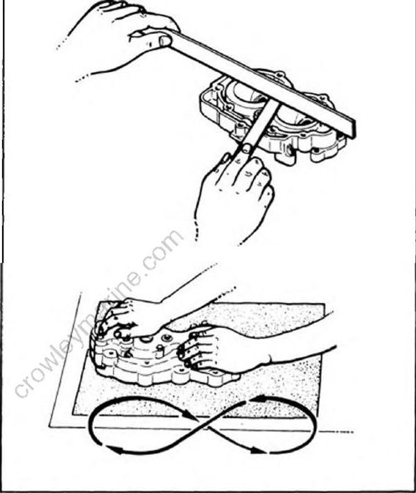
- Check the cylinder head warpage with a straightedge as shown.
The warpage should not exceed the specified limit; if necessary, resurface the cylinder head.
Cylinder head warpage: Less than 0.1 mm (0.004 in)
- Correct by re-surfacing as follows:
Place 400 ~ 600 grit wet sandpaper on the surface plate and re-surface the head using a figure-eight sanding pattern. Rotate the head several times to avoid removing too much material from one side.
Cylinder body and crankcase
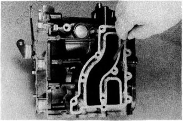
- Visually check the cylinder walls for scratches. If vertical scratches are evident, the cylinder wall should be rebored or the cylinder should be replaced.
- Remove any deposits from the cylinder exhaust port.
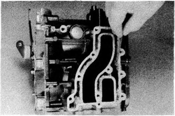
- Check the cylinder body water jacket and cooling water passages for dirt, salt, sand, or other deposits and clean as required. Also patch up any part from which anti-corrosion paint has come off. If the water jacket or passage is corroded, replace the cylinder assembly (cylinder body and crankcase).
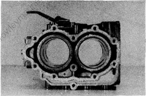
- Hone the cylinder bore using a hone with fine stones. Hone no more than required to remove all wear marks.
| Cylinder bore | Cylinder bore |
|---|---|
| Standard | Wear limit |
| 56 + 0.02 mm | 56.1 mm (2.209 in) |
| (2.20 + 0.0079 in) | 56.1 mm (2.209 in) |
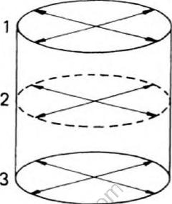
- Using a cylinder gauge set to standard bore size, measure the cylinder. Measure front-to-rear and side-to-side at top, center and bottom just above the exhaust port.Take minimum and maximum measurements.If over tolerance and not correctable by honing,rebore to next over-size.
| Maximum allowable taper: 0.08 mm (0.003 in) |
|---|
| Maximum allowable out-of-round: 0.05 mm (0.002 in) |
- Drainless mechanism
The lower bearing is connected to the upper bearing by a rubber tube. Disconnect the tube on the upper bearing sideand breathe in and out of its open end.When breathing in, the valve should close and no air flows.
When breathing out, the valve should open, allowing air to flow.Therefore, if air flows when you inhale, the valve is faulty and should be replaced.
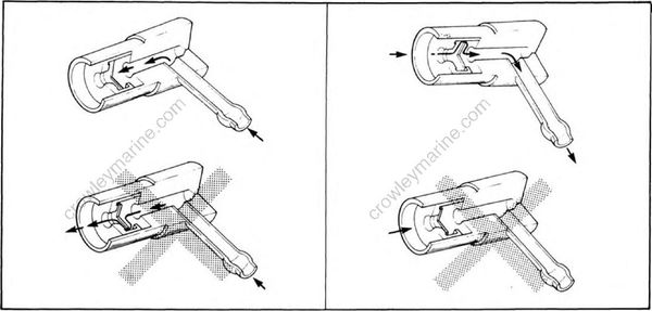
Check valve replacement
a. Pull out the check valve using pliers.
NOTE: Do not pry the valve out. Remove it by rotating.
b. Throughly clean the hole of sealing compound.
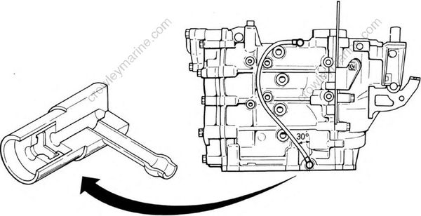
c. Coat a new check valve, insert with LOCKING AGENT and drive it in.
NOTE: The insert should be driven in so that the delivery pipe is inclined 30° toward the cyliner head.
Piston
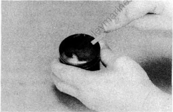
Remove any carbon deposits from the piston crown.
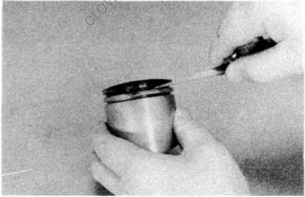
Carefully remove any carbon deposits from the ring grooves with the filed end of a ring.
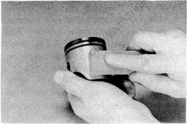
Remove all score marks and lacquer deposits from the sides of the piston using 600 ~ 800 grit wet sandpaper. Sand in a crisscross pattern. Do not sand excessively.
Piston clearance
- Measure the outside diameter of the piston at the piston skirt.
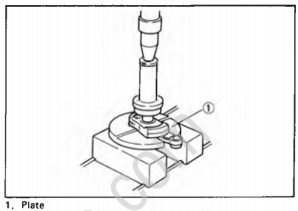
Measurement should be made at a point 10 mm (0.4 in) above the bottom edge of the piston. Place the micrometer at right angles to the piston pin.
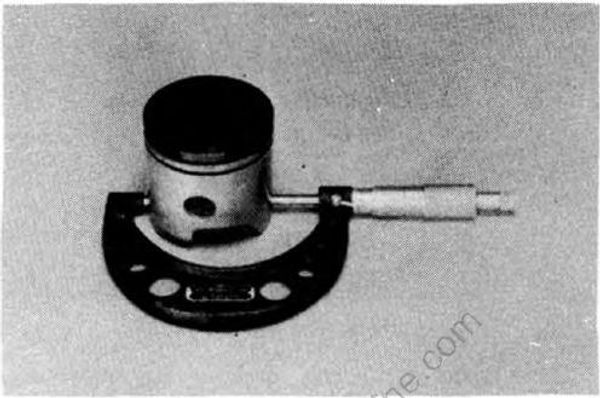
- Determine piston clearance as follows:
Minimum bore measurement — Maximum piston measurement = Piston clearance
EXAMPLE:
56.020 mm (2.206 in) -55.980 mm (2.204 in) + 0.040 mm (0.0016 in)
Piston clearance.
0.035 ~ 0.040 mm
(0.0014 ~ 0.0016 in)
Piston ring
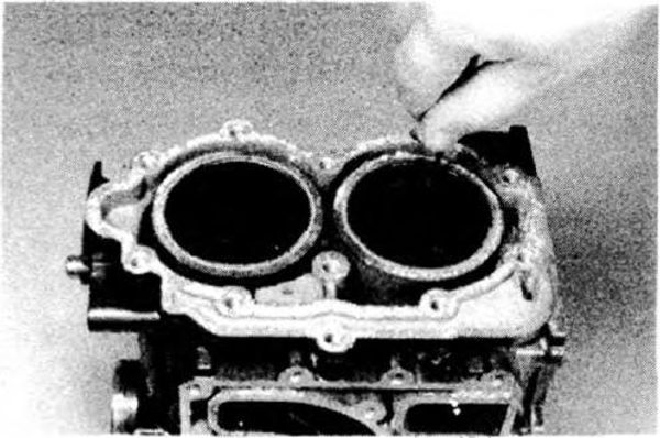
- Measure the end gap of each piston ring. Insert a ring into the cylinder and push it approximately 20 mm (0.8 in) into the cylinder. Push with the piston crown so the ring will be at a right angle to the cylinder bore.
- Measure the ring end gap with a feeler gauge. If the end gap exceeds tolerance, replace the whole set of rings.
Ring end gap installed:
Top/Second
Minimum: 0.15 mm (0.006 in)
Maximum: 0.35 mm (0.014 in)
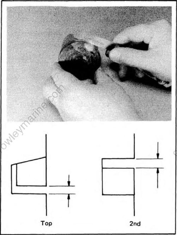
- Piston ring/ring groove fit must have correct clearance. If the piston and ring have already been used in the engine, the ring must be removed, the ring groove cleaned of carbon, then the ring should be reinstalled. Use a feeler gauge to measure the gap between the ring and the ring groove land.
| Side clearance | Top | 0.04 ~ 0.08 mm (0.0016 ~ 0.0030 in) |
|---|---|---|
| Side clearance | 2nd | 0.04 ~ 0.08 mm (0.0016 ~ 0.0030 in) |
Piston pins and bearings
- Apply a light film of oil to the pin and the bearing surfaces. Install in the connecting rod small end to inspect for wear. Check for play. There should be no noticeable vertical play. If play exists, check the connecting rod small end for wear. Replace the pin, connecting rod and/or bearing as required.
- The piston pin should have no noticeable free play in the piston. If the piston pin is loose, replace the pin and/or piston.
- Check the pin and bearing for signs of heat discoloration. If excessive (indentation on pin, etc.), replace the pin and bearing.
- Check the piston pins and bearings for fretting or pitching and replace them as required.
Crankshaft
- Check the connecting rod axial play at the small end to determine the amount of wear of the crank pin and the bearing at the big end.
If small end play exceeds tolerance, disassemble the crankshaft and check the connecting rod, crank pin, and big end bearing.
Replace defective parts. Play after reassembly should be within specification.
Rod axial play: 2 mm (0.08 in)
- Check the connecting rod side clearance at the big end.
If clearance exceeds tolerance, disassemble the crankshaft and replace any worn parts. Big end clearance should be within specification.
| Rod side clearance | Rod side clearance |
|---|---|
| Minimum | Maximum |
| 0.20 mm (0.008 in) | 0.70 mm (0.028 in) |
- Crankshaft runout
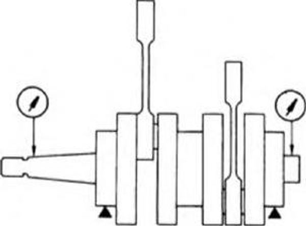
a. Support the crankshaft at both ends on V-blocks. Rotate the crankshaft in the V-blocks and measure the runout at the main bearing journals. Use a dial gauge.
b. Check crankshaft assembly runout (misalignment of crankshaft parts).
Dial gauge readings should be within specification.
Correct any misalignment by tapping the flywheel with a brass hammer and/or by using a wedge.
| Deflection tolerance | Deflection tolerance |
|---|---|
| Left side | Right side |
| 0.03 mm (0.001 in) | 0.03 mm (0.001 in) |
Reed valve assembly
Inspection
- Inspect the reed petals for signs of fatigue cracks. The reed petals should fit flush or nearly flush against the neoprene seats. If in doubt as to sealing ability, apply suction to the carburetor side of the assembly. Leakage should be slight to moderate.
- Check valve stopper clearance. If beyond tolerance, adjust the stopper or replace as required.
Valve stopper clearance:
9.9N : 1.3 mm (0.05 in),
15N: 4 mm (0.16 in)
If clearance is 0.1 mm (0.004 in) more or less than specified, replace the valve stopper.
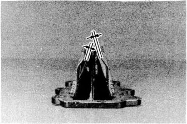
Check the reed valve for bending and, if beyond tolerance, replace.
Reed valve bending limit: 0,2 mm (0.008 in)During reassembly, clean the block, reed and stopper plate thoroughly. Apply a holding agent, such as "Loc-Tite," to the threads of the Phillips screws. Tighten each screw gradually to avoid warping.
Torque: 1 Nm (0.1 m•kg, 0.7 ft•lb)
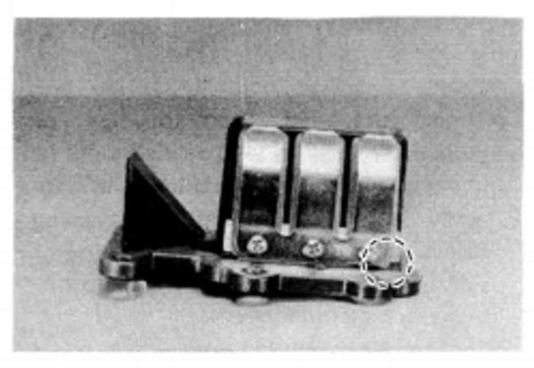
NOTE: During reassembly, note the cut in the lower corner of the reed and stopper plate. Use as an aid for direction of reed installation.
Crankshaft main bearings
Thoroughly clean the crankshaft, sparingly oil both the upper and lower ball bearings and slowly turn the outer races with your hand. If rough spots are noticed, replace the ball bearing (s).
Removal
As shown, hold the upper and lower bearings with the bearing separator and force the crankshaft out with a press.
CAUTION: When removing the crankshaft, hold with your hand so that it will not fall off.
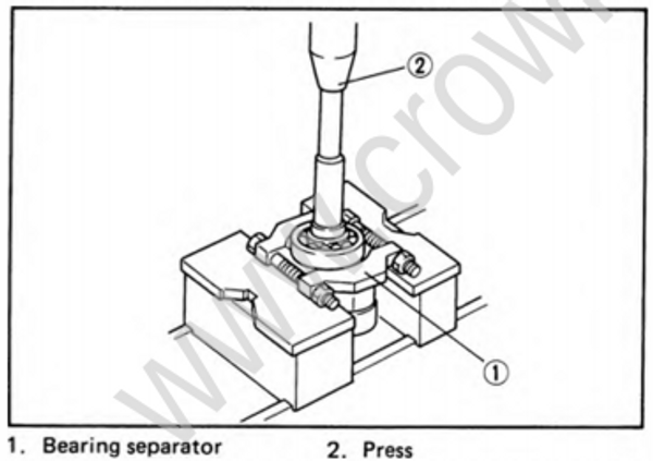
- Bearing separator
- Press
CAUTION: When press-fitting the bearing, be sure to force the inner race. Do not force the outer race.