ADJUSTMENT POWER HEAD
Spark plug
Check electrode condition and wear, insulator color and electrode gap.
Clean the spark plug with spark plug cleaner if necessary. Use a wire gauge to adjust the plug gap to specification.
If the electrode becomes too worn, replace the spark plug.
When installing the plug, always clean the gasket surface, wipe off any grime that might be present on the surface of the spark plug, and torque the spark plug properly.
Standard spark plug:
150 : B-7HS10
175 : B-8HS10
200 : B-8HS10
Spark plug gap : 0.9-1.0 mm (0.035 0.040 in)
Spark plug tightening torque : 20 Nm (2.0 m.kg, 14 ft.lb)
Ignition timing adjustment
Adjustment of the link length
- Remove the joint link between the flywheel magneto base and magneto control lever.
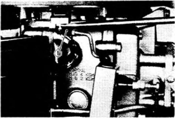
- Joint link
- Remove the joint link between the magneto control lever and throttle cam.
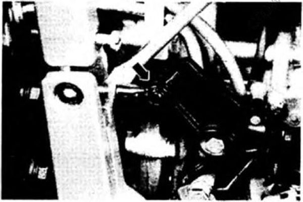
Adjust the lengths of magneto control lever link and throttle cam control link.
Adjust the lengths of magneto control lever stopper for full advanced side and full-retarded side.
1. The nut on the full-retarded side should be 2.5 mm (0.1 in) off from the end of the magneto control lever.
2. These dimensions are temporary settings, so they can be changed when ignition timing is adjusted.
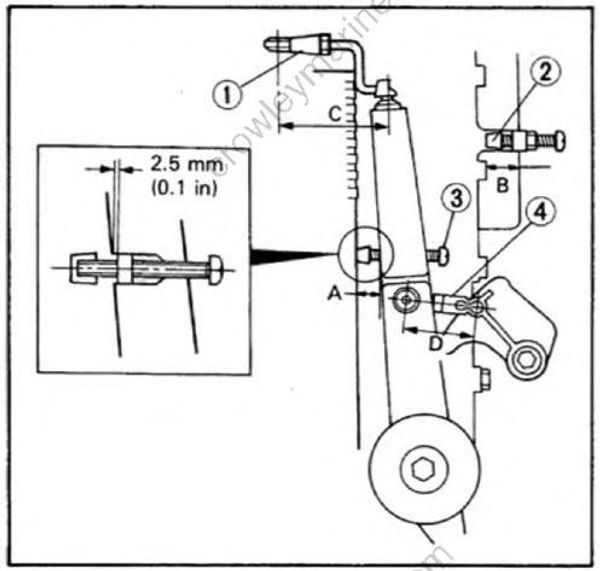
- Magneto control link
- Full-advanced adjust screw
- Full-retareded adjust screw
- Throttle cam control link
| 150HP/175HP/200HP | |
|---|---|
| A | 16±0.5 mm (0.63±0.02 in) |
| B | 18±0.5 mm (0.71 ±0.02 in) |
| C | 62 mm (2.44 in) |
| D | 42 mm (1.65 in) |
- Connect the magneto control link to the magneto control lever and magneto base.
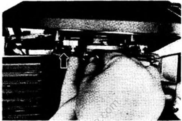
Do not connect the throttle cam control link until ignition timing adjustment is complete.
Timing plate adjustment
Remove the spark plugs from the cylinders.
Install a dial gauge in the spark plug hole in the No. 1 cylinder.
For easy timing plate adjustment, it is advisable to remove the spark plugs from all cylinders.
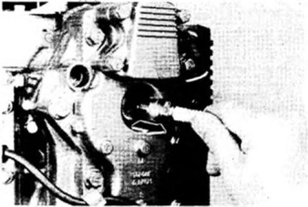
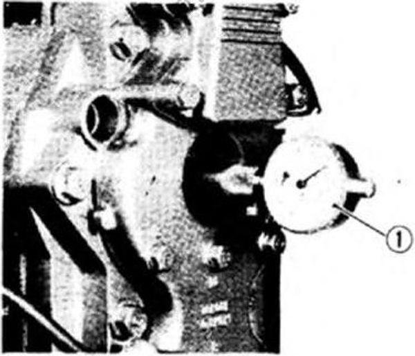
- Dial gauge
- Slowly turn the C.D.I. magneto rotor clockwise, and stop it when the piston is at TDC.
Be sure to turn the magneto rotor clockwise when the engine is mounted on the upper case. Otherwise, the impeller blade will be twisted the other way round, thus reducing pump performance.
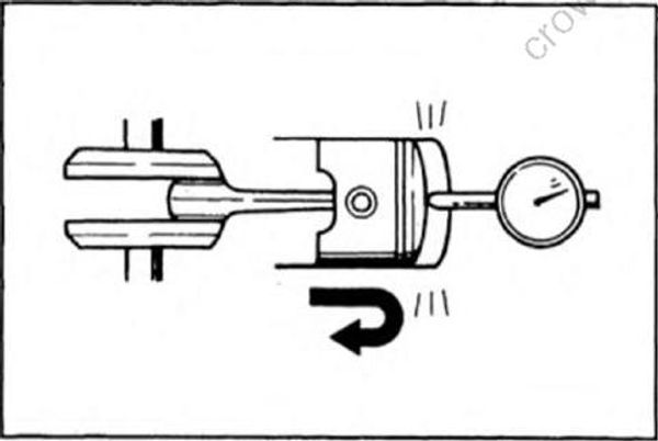
- If the end of the timing plate is not align ed with the TDC mark on the CDI magneto rotor, loosen the timing plate set screw, align the timing plate end with the TDC mark, then tighten the screw.
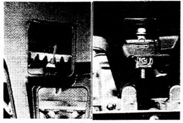
After tightening the screw, paint the screw head to keep other unauthorized persons from tampering with the screw.
- Remove the dial gauge from the No.1 cylinder and install the spark plugs for each cylinder.
Ignition timing adjustment
1. Before adjusting the ignition timing, be sure to adjust or check the link length and timing plate.
2. Before adjusting the ignition timing, be sure to warm up the engine.
3. The engine is water-cooled and therefore, it must be started in a test tank or mounted on a boat when it is started.
1. When adjusting the ignition timing, be careful not to allow your hand, clothes, or hair to touch any rotating parts such as the flywheel.
2. Never attempt to remove the flywheel cover, as the flywheel is rotating. Adjustment is possible without removing the cover.
3. Never touch any electrical parts, since high voltage current flows through them.
Full-retarded position
- Clip the timing light at the No. 1 cylinder high-tension lead.
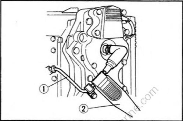
- No.1 cylinder high-tension lead
- Timing light clip
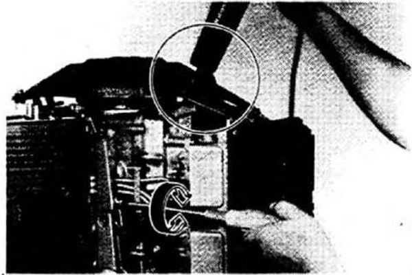
- Start the engine, and move the magneto control lever to the full-retarded side so that the full-retarded adjust screw contacts the stopper.
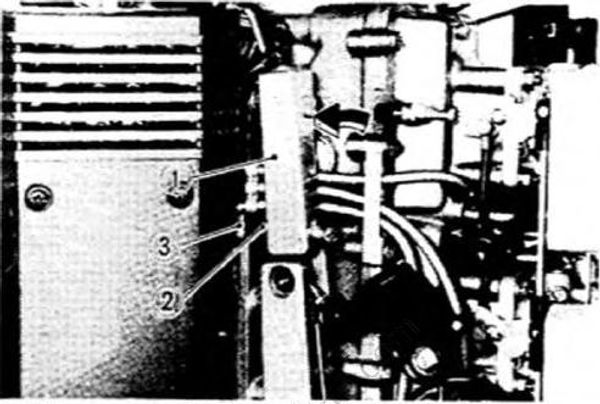
- Magneto control lever
- Full-retarded adjust screw
- Stopper
- Direct the timing light to the timing plate and the timing indicator and make sure of the timing indicator to which the timing plate points.
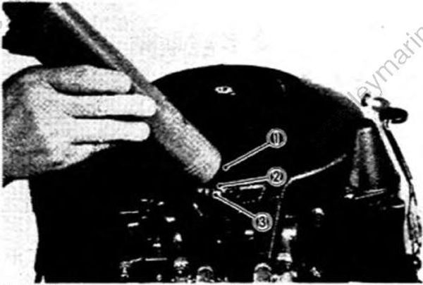
- C.D.I. magneto rotor
- Timing indicator
- Timing plate
Turn the adjust screw until it contacts the stopper.
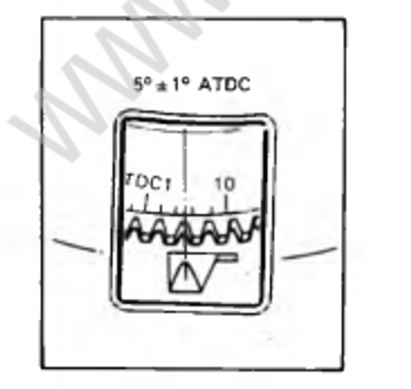
- If the timing plate is out of alignment with the specified position on the timing indicator on the flywheel rotor, adjust the full-retarded side adjust screw so that the timing plate aligns with the specified position.
Specified ignition timing : ATDC 5±1°
Turning the adjust screw clockwise advances the ignition timing. Earlier than 5° ATDC Turning the adjust screw counterclockwise retards the ignition timing. Later than 5° ATDC
Full-advanced position
1. After adjusting the full-retarded position, adjust the full-advanced position.
2. Do not connect the throttle cam control link.
3. As the engine speed increases, be careful not to touch any rotating parts.
- Move the magneto control lever to the full-advanced side so that the magneto control lever contacts the full-advanced adjust screw.
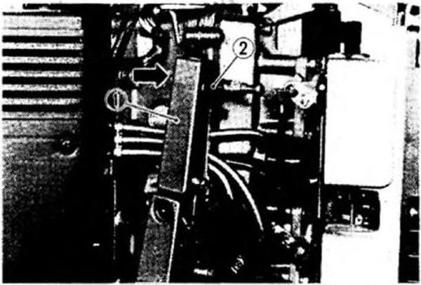
- Magneto control lever
- Full-advanced adjust screw
- Direct the timing light to the timing plate and the timing indicator and make sure of the timing indicator to which the timing plate points.
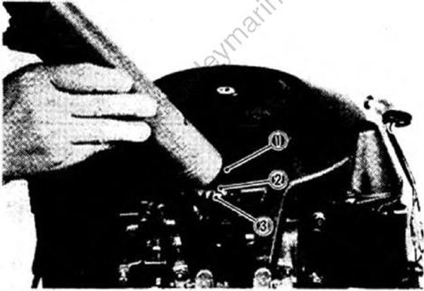
- C.D.I. magneto rotor
- Timing indicator
- Timing plate
Be sure that the magneto control lever is in contact with the adjust screw.
- If the timing plate is off the specified position on the indicator, make an adjustment by turning the full-advance side adjust screw so that the timing plate aligns with the specified position.
Specified ignition timing :
150HP : 24° ±1° BTDC
175HP 200HP : 22±1° BTDC
Turning the adjust screw clockwise retards the ignition timing.
Later than 24° BTDC (150HP)
22° BTDC (175HP/200HP)
Turning the adjust screw counterclockwise advances the ignition timing.
Earlier than 24° BTDC (150HP)
22° BTDC (175HP/200HP)
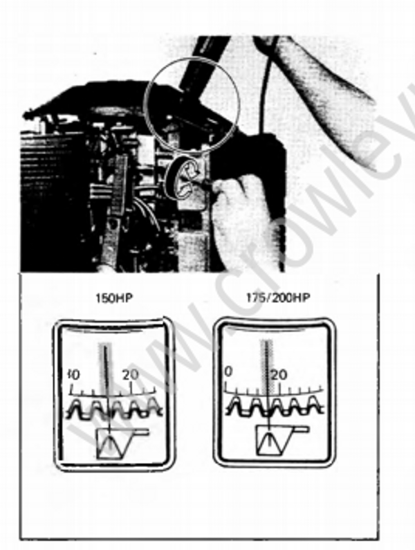
- After adjusting ignition timing to specified, tighten the full-advanced adjust screw locknut, and stop the engine.
Throttle linkage adjustment in carburetor
- Loosen the idle adjust screw on the uppermost carburetor, and part the screw from the throttle arm stopper.
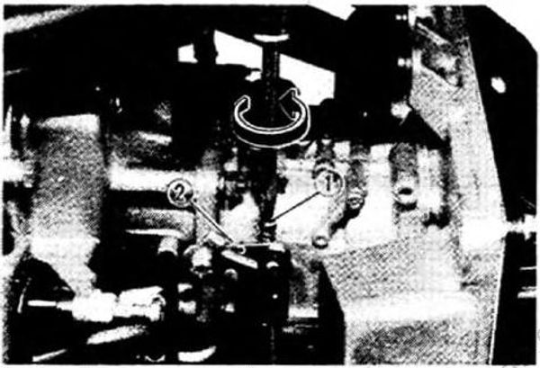
- Idle adjust screw
- Throttle arm
- Loosen the throttle arm adjust screws (left-hand) on the upper and lower carburetors, and make sure all the throttle valves in the upper, middle, and lower carburetors are fully closed.
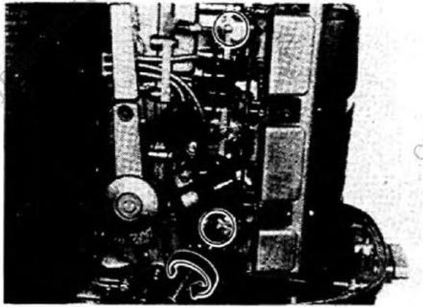
- Remove the play of the throttle link and throttle arm ball joint so that the upper, middle, and lower throttle valves operate simultaneously, and tighten the throttle arm adjust screws (left-hand) on the upper and lower carburetors.
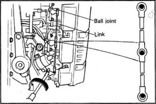
- Tighten the idle adjust screw until contacts the throttle arm stopper. From this position, tighten the idle adjust screw one turn.
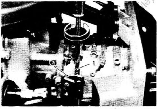
Oil pump link adjustment
- Remove the link connecting the oil injection pump to the carburetor.
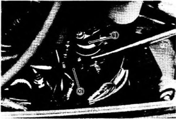
- Oil injection pump
- Link
- Loosen the idle adjust screw and part the screw from the throttle arm stopper screw.
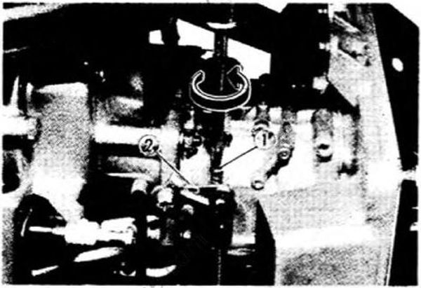
- Idle adjust screw
- Throttle arm
- Set the oil injection pump stroke adjust arm on the full closed side.
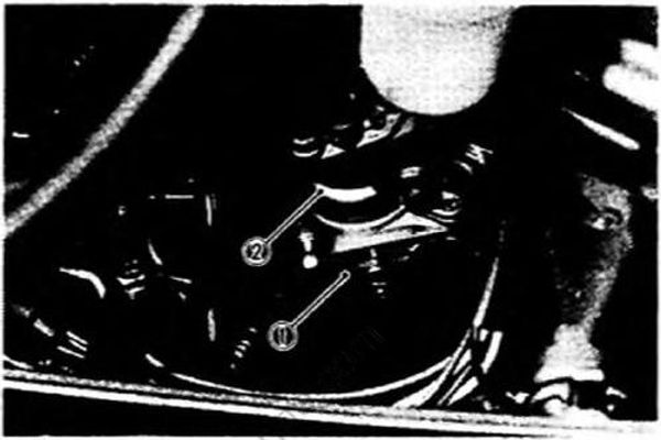
- Oil pump arm
- Oil injection pump
- Adjust the length of the link, connecting the carburetor to the oil pump, on the oil pump side, and connect the link to the oil pump arm.
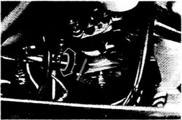
- Adjust the carburetor link properly according to the "Throttle linkage adjustment in carburetor." Refer to page 2-23.
Adjusting the idling r.p.m.
- Connect the tachometer leads to the remote control box leads.
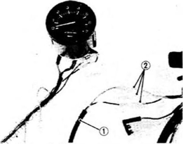
- Tachometer leads
- Remote control box leads
- Start the engine, and move the magneto control lever to the full-retarded side so that the full-retarded adjust screw contacts the stopper.
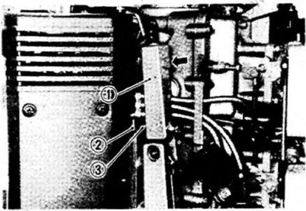
- Magneto control lever
- Full-retearded adjust screw
- Stopper
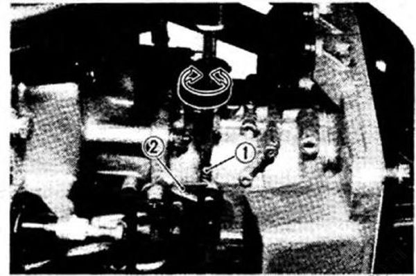
- Direct the timing light to the timing plate, and make sure ignition is timed to 5° ± 1 ° ATDC. Next, adjust the throttle opening by turning the idle adjust screw so that the engine speed is specified.
Idling r.p.m : 800 ±25 min-1 (r/min)
Adjusting the pickup timing
- Move magneto control lever slightly to the full-advanced side so that ignition timing is set at 4° ATDC. Use a timing light for this adjustment.
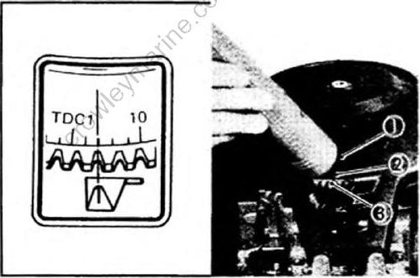
- C.D.I. magneto rotor
- Timing indicator
- Timing plate
- Bring the accelerator cam to contact lightly with the throttle lever roller. (The throttle valve should not open.) In this case, the stamp line on the accelerator cam must align with the center of the throttle lever roller. If not, loosen the throttle lever adjust screw (left-hand), and align the stamp line on the cam with the center of the roller, then tighten the screw (left-hand).
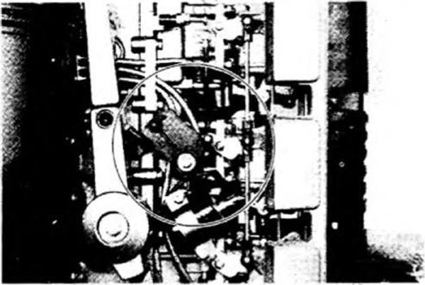
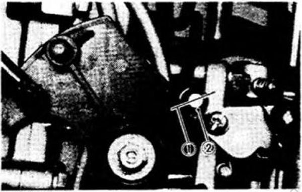
- Stamp line
- Throttle roller
Do not connect the throttle link.
- Adjust the accelerator link properly and connect magneto control lever to the accelerator cam.
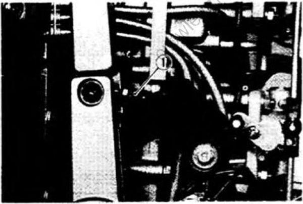
- Accelerator link
Ignition timing adjustment without using a timing light
1. On the 150HP, 175HP, 200HP, ignition timing should be adjusted using a timing light in principle. Therefore, the ignition timing adjustment using no timing light is regarded as an expedient.
2. When adjusting the ignition timing without using a timing light, remove the spark plugs from all cylinders.
Adjustment the link length
Refer to page 2-25.
Timing plate adjustment.
Refer to page 2-26.
Full-retarded position
- Slowly turn the flywheel clockwise to align the timing plate with "5° ATDC" on the timing indicator.
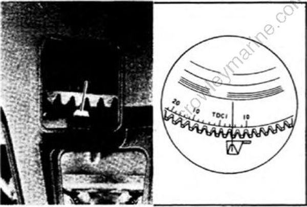
- Move magneto control lever to the full retarded side so that the full-retarded adjust screw contacts the stopper.
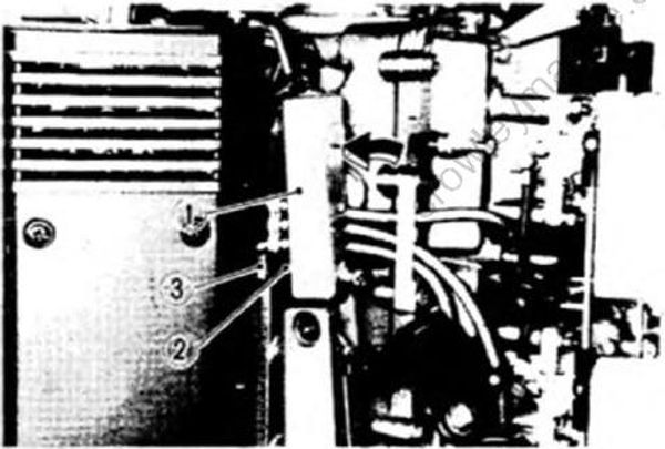
- Magneto control lever
- Full-retarded adjust screw
- Stopper
- Check to see that the projection on the end of the pulser assembly arm aligns with the timing mark stamped on the rotor. If not aligned, bring them to align by turning the full-retarded side adjust screw.
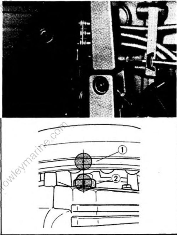
- Flywheel magneto rotor
- Pulser assembly arm
Adjusting the pickup timing
- Slowly turn the flywheel counterclockwise from the full-retarded position so that the “4° ATDC" on the rotor aligns with the timing plate.
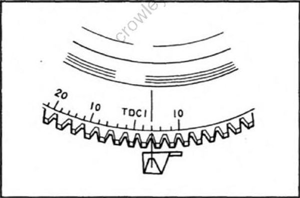
- Move magneto control lever so that the end of the pulser assembly arm aligns with the ignition mark on the back of the rotor.
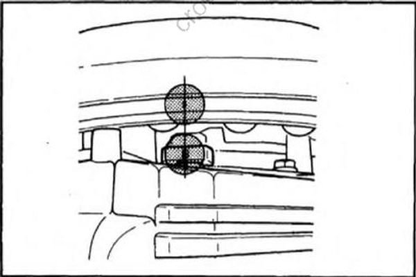
- Bring the accelerator cam to lightly contact the throttle lever roller. (The throttle valve should not open.)
In this case, the stamp line on the accelerator cam must align with the center of the throttle lever roller. If not, loosen the throttle lever adjust screw (left-hand), and align the stamp line on the cam with the center of the roller, then loosen the screw (left-hand).
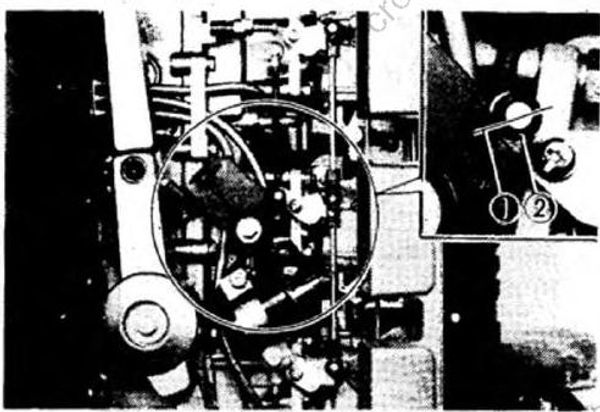
- Accelerator cam
- Throttle lever roller
- Adjust the accelerator link length and connect magneto control lever to the accelerator cam.
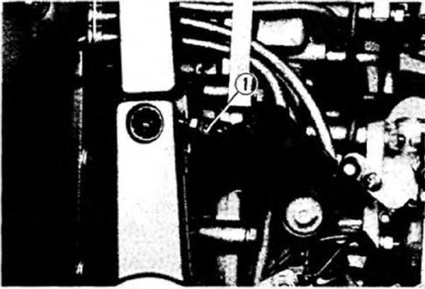
- Accelerator link
Full-advanced position
- Further turn the flywheel counterclockwise from the pickup timing position so that the specified on the rotor aligns with the timing plate.
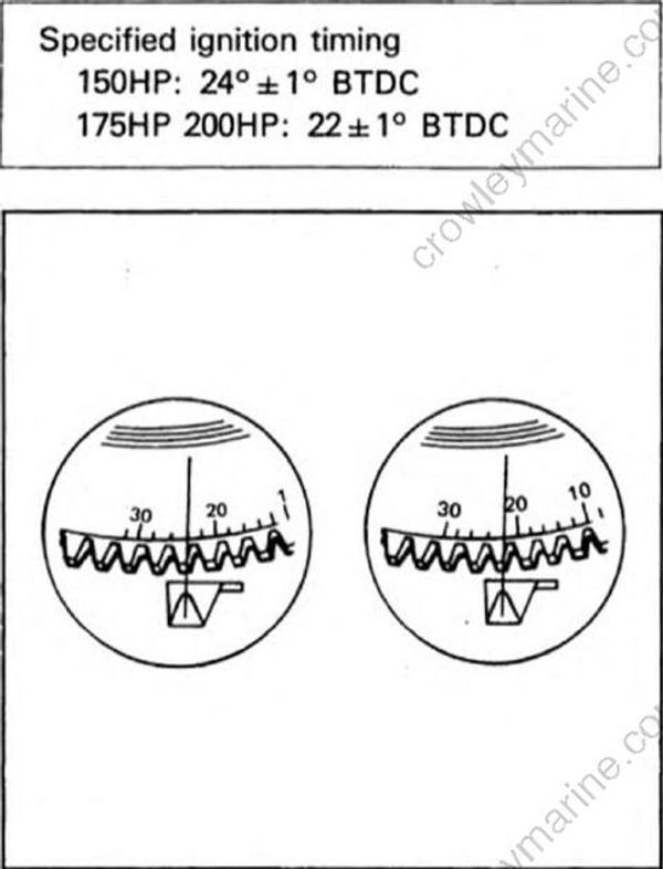
- By moving magneto control lever bring full-advanced adjust screw to contact the stopper.
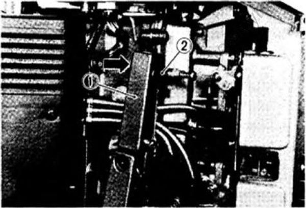
Magneto control lever
Full-advanced adjust screw
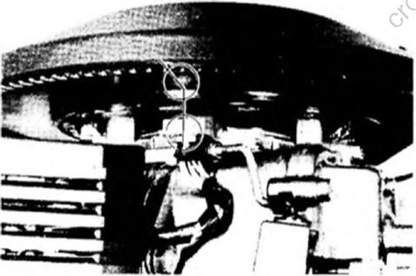
Check to see that the stamp line on the reverse side of the flywheel rotor aligns with the projection on the end of the pulser assembly arm. If not aligned, bring them to align by turning the adjust screw, and lock the screw with the lock nut.

Idle speed adjustment
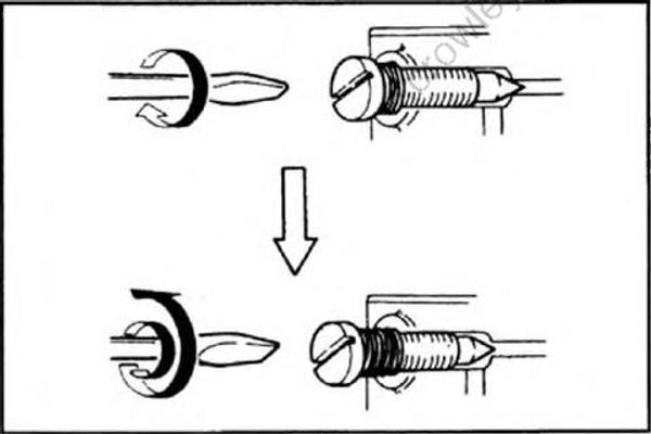
Turn the pilot screw until it is lightly seated.
Turn out the pilot screw to specification.
Pilot screw specs:
| Model | I.D. Mark | Turns Out |
|---|---|---|
| 150 | 6G400 | 2-3/8 ± 1/4 |
| 175 | 6G500 | 2-1/8 ± 1/4 |
| 200 | 6G600 | 2-1/8 ± 1/4 |
| 150 | 6G401 | 1-1/4 ± 1/4 |
| 175 | 6G501 | 1-1/4 ± 1/4 |
| 200 | 6G601 | 1-3/8 ± 1/4 |

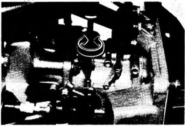
Start the motor, and warm it up for a few minutes.
Set the motor idle speed to the specified level by adjusting the throttle stop screw. Turning the throttle stop screw in (clockwise) increases the motor speed; turning it out (counterclockwise) decreases the motor speed. Use a tachometer for checking and adjusting the motor speed.
Idle speed : 800±25 min-1 (r/min)
If the ignition timing has been adjusted to 5° ± 1° ATDC, readjust the ignition timing on the full-closed side.
Trim tab adjustment
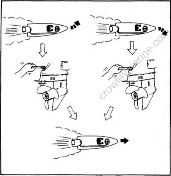
The trim tab plays an important role in steering the boat straight ahead. The rotation of the propeller works as if the boat were steered to the right and therefore, it is necessary to off set such a tendency of steering by holding the helm firmly. The trim tab helps the boat move straight ahead. When the motor is shipped from the factory, the trim tab is set one division off to the port side.
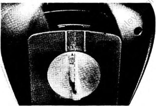
- Trim tab
By taking into account the force working against the helm when the boat runs at full throttle, adjust the trim tab.
- If the steering wheel turns easily to the left, turn the trim tab to the left.
- If the steering wheel turns easily to the right, turn the trim tab to the right.