

Maintenance And Lubrication
Any debris jammed between the impeller and casing will fall out. Attempting to turn the flywheel either direction may be personally too difficult due to the added torque required to overcome the valve train. Removing the intake will render the best results in most cases.
Do not attempt to use a wrench on the flywheel lock nut to rotate the flywheel backward because you may loosen the nut. Proper tightening, while afloat without the proper tools, is not possible, and major damage could occur to your motor.
Be sure to remove the spark plug wires before removing the intake screen.
Be aware that gravel passing through the pump will wear and round off the leading edges of the impeller blades. For maximum performance, file these edges occasionally to keep them as sharp as when new (see Impeller in the Maintenance section).
Cavitation Damage
Rough edges caused by rocks and gravel will lead to additional damage of the impeller if they are not removed by filing them off in some way. Turbulence across the blades behind these rough edges will result in low pressure areas that will allow small pockets of water to boil. These pockets of steam later collapse releasing a large amount of energy that erodes the impeller surface. Such damage spots are referred to as cavitation burns.
Your jet drive is equipped with a shear key to protect it in the event of a rock jam. This key can be located by removing the water intake housing and the drive shaft nut. Before replacing the key, note the position of the impeller shim washers, and replace them in the same order as removed. Tighten the impeller nut as described in the assembly section of this manual.
Intake Blockage
Occasionally, when either holding or proceeding slowly upstream in a fast-moving, shallow area, you will lose power. This is usually caused by suction holding flat rocks, lily pads, paper, or other debris against the intake grille and restricting water intake. If you quickly stop the motor and restart it, this sort of material will fall away and full power will be restored. If rocks have been jammed between the grille bars, turn off the engine and pry them out with a suitable tool.
Mooring
If you tie your boat up at a sandy beach, where the action of waves causes the boat to rise and fall, be sure to tip the motor up out of the water. Failure to do this will result in the buildup of sand inside the intake housing and around the impeller. It is advisable to tie the boat up and shut off the motor any time it is likely not to be used for a sustained period of time.
Throttle Use
As with any outboard, you will get maximum economy by not running at full throttle. Running at one-third to one-half throttle, with the boat at a steep angle, leaving a large wake, will also waste fuel.
Tilt and Trim Use
It is important for you to learn how to use the Power Trim and Tilt function properly, on those models equipped with this feature. The Power Trim and Tilt function is convenient for use while drifting, and when operating at low throttle in very shallow areas. When under power, however, the engine should not be trimmed out in an effort to gain speed as is done with conventional propeller-driven motors. When planing, the engine drive shaft should be either vertical or tucked under, toward the boat in order to provide a good scoop angle for the water intake grille. Tilting the motor outward, beyond a vertical position, reduces the scoop angle and can cause impeller slippage, as well as cavitation burns on the impeller blades. Manual-tilt models should be adjusted with the tilt pin to provide a vertical engine position while planing.
MAINTENANCE AND LUBRICATION
General
Occasionally, check all mounting bolts, intake screws, linkage connections, etc.; to be sure they are tight.
Bearing Lubrication
The need for frequent lubrication of your Yamaha Jet Drive Outboard cannot be overemphasized. Yamaha recommends lubrication after each day's use and every 10 hours of operation. Make greasing a regular part of your cleanup. Use only Yamalube Marine Grease or NLG1 greases.
Do not use a pneumatic grease gun. Over pressurizing the grease chamber may cause the seals to move out of position.
The lubrication fitting for the drive shaft bearing is located at the top-left-front of the jet drive casing (see Location of Main Components section, page 2, top illustration). It is capped with a fitting on the end of the excess-grease exit hose. Using a grease gun, pump in enough grease to just fill the hose. To remove the hose from the fitting, press the end cap upward and toward the casing; to refit it, press the hose end cap over the fitting.
Every 30-40 hours, pump in enough extra grease to purge any moisture. The texture of the old grease coming out of the hose will provide you with an indication of conditions inside the bearing housing. A gradual increase in moisture content indicates seal wear. If the grease begins to turn a dark, dirty gray, the bearing(s) and seals should be inspected and replaced as necessary. Some discoloration of the grease is normal during the break-in period on a new set of seals.
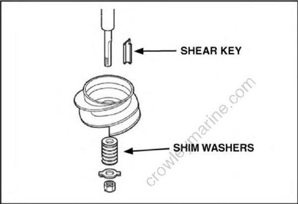
Impeller Clearance Setting
There are several shims (washers) between the impeller and the locking tab that dictate the impeller to casing clearance. After operation in water with a sand or gravel bottom this clearance may enlarge. If the clearance exceeds 1/32", moving one or more shims to the top of the impeller will allow compensation for this wear. Adjusting the shims in this way locates the impeller further into the tapered casing to reduce the clearance. Be sure to grease the drive shaft to impeller mating surface, the key, sleeve, and drive shaft threads during reassembly. See the Assembly Instructions for your model later in this manual for more detailed instructions.
Impeller Difficult to Remove
The drive shaft and impeller are separated by a Delrin® sleeve to prevent corrosion. If you experience difficulty removing the impeller, it is most likely due to the sheer key being wedged on the flat of the drive shaft, not corrosion.
To relieve this wedging, rotate the impeller on the shaft in the normal direction of rotation while the drive shaft is stationary. Perpendicularly align the keyway in the impeller with the flat on the shaft. This can be done with a soft hammer on a block of wood, or by using a C clamp on one blade and bumping that.
The impeller is free for removal in this position. If necessary, use two wood levers, about 3/4" x 1-1/2" x 12", wedged under the blades against the housing flanges to assist with removing the impeller.
Linkage Adjustment
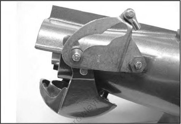
Occasionally, check the adjustment of the shift link age. In “Forward,” the reverse gate should be firmly locked. This will eliminate rattle and prevent wave action from accidentally shifting the gate into reverse (see Adjustments section for the proper procedures.)
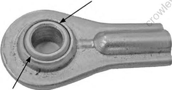
The shift cable ball joints should be lubricated with Yamalube Marine Grease at least once every six months (see above photo).
Salt Water Operation
Both aluminum and stainless steel have been extensively used in the construction of your jet drive. These and other materials have been either treated or are inherently resistant to corrosion. In addition, the intake grille, special key, and exhaust tube are galvanized to further minimize corrosion. However, it is highly recommended, that when not in use the motor be tipped or trimmed up so the jet drive casing is out of the water.
If your jet drive is used in salt water, it would be best if all fasteners were removed and greased at least once every six months. Doing so will seal water out of the thread gaps and aid the prevention of corrosion. Failure to do this may result in the hardware being difficult, if not impossible, to
remove at a later date.
STORAGE
Power Unit
Consult your Outboard Owner’s Manual for preparing the motor part of your jet drive for storage.
Jet Unit
Grease the drive shaft bearing by pumping in enough extra grease to purge any moisture. Additionally, remove and refit the jet drive impeller, greasing the bore, key, and plastic sleeve. In addition, clean and grease all hardware.
ADJUSTMENTS
Shift Cam Assembly with Neutral Adjustment
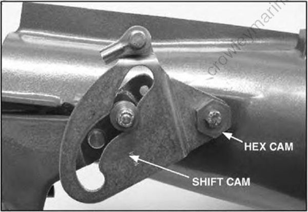
A shift mechanism comprised of a shift cam with an adjustable pivot point has been incorporated. When the pivot point is properly located by the hex cam eccentric, in the neutral position, the forward thrust of the jet-driven outboard will be negligible.
Neutral Adjustment of All Models
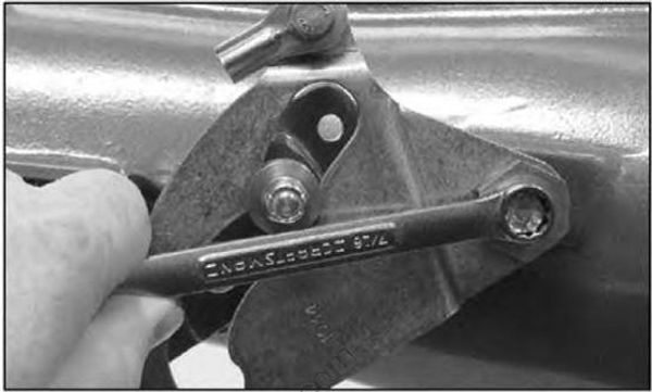
- Loosen the inner pivot bolt securing the Hex Cam.
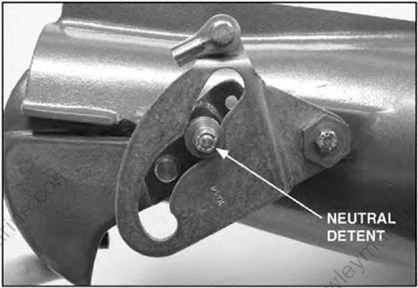
- Using light pressure against the gate, move it upward toward reverse until the cam roller is nested in the neutral detent in the forward side of the cam slot. (During operation jet pressure will push the gate toward reverse and cause the roller to maintain contact with the front edge of the cam.)
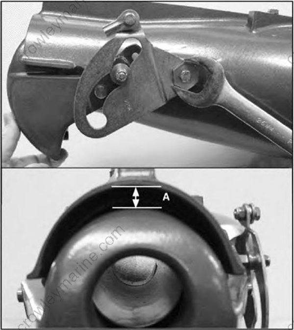
- Hold the gate in this position while rotating the Hex Cam either direction until the gate clears the underside of the nozzle hood by measurement (A). This measurement should be 15/32 for pumps with a 2-1/2" O.D. exhaust pipe and 9/16 for those with 2" O.D exhaust pipes
