

F40/F60 Assembly (AJ Model)

Parts List
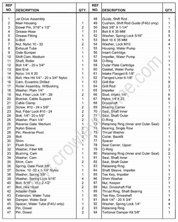
Instructions
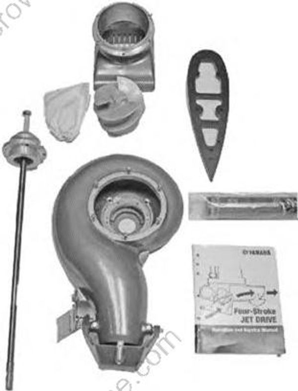
- Installing the jet unit onto the outboard can be performed while the engine is mounted horizontal in the crate frame or after mounting the engine on the boat. In any case, the first step should be to open the jet pump box and locate all the major components.
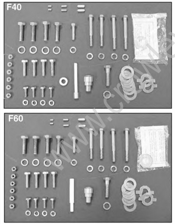
- Open the hardware bag packed with the intake screen and separate all the components in like groups for easy identification (refer to the above appropriate photo).
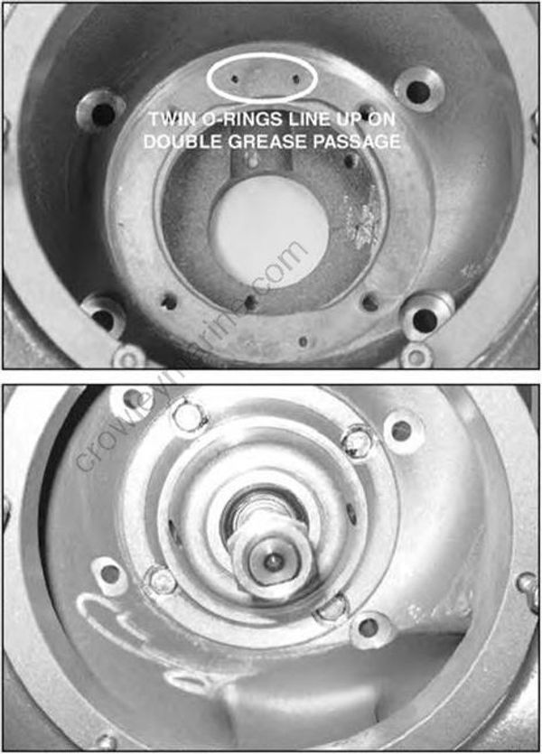
- Turn the pump housing upside down and install the drive shaft assembly noting the alignment of the sealing O-rings with the two grease passages in the housing. The bolt pattern is staggered to ensure their alignment. Locate the four 1/4" X 20" X 3/4" retaining bolts and their lock washers from the hardware bag. Apply grease to the bolt threads and torque them to 8 ft-lb. pattern is staggered to ensure their alignment.

The 4-stroke jet units must use the specifically designed water pump housing that is supplied with the engine. This housing has a bleed hole to prevent over-cooling. The housing is a component of a special water pump kit that is located inside the rigging hardware box strapped to one of the vertical supports of the engine carton.
Failure to use the above housing will result in engine failure.
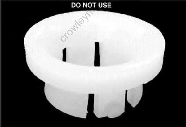
- Retrieve the water pump kit from the rigging box that accompanied the outboard motor. Open the bag containing the impeller and discard the white nylon cover shown above that retains the grommet on the standard lower unit models. Never use this component on a jet unit as it will push the water tube out of position and result in an overheat condition at idle.
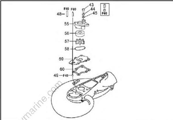
- (F40 Only)
Locate the shift rod guide (48 & 49 lower, previous column) made from a white dowel from the hardware bag and remove the clear hose like end (49). Push the clear hose down into the hole in front of the water pump mounting area. Retain the plastic dowel for installation after the outer plate.
Position the water pump base gasket on the deck of the jet unit followed by the outer plate. Then, install the remainder of the water pump.
Push the shift rod guide dowel into the hole in front of the water pump housing. The F40 guide goes through a hole in the outer plate and inside the clear sleeve.
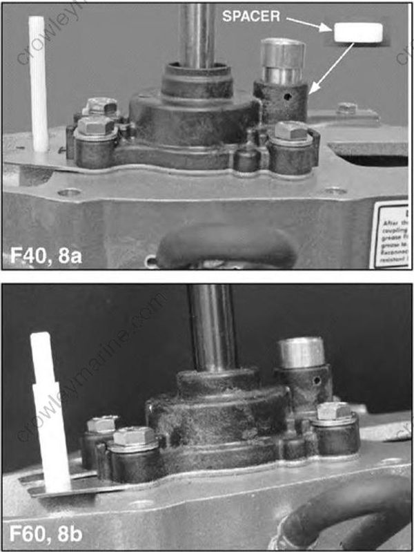
8a. (F40 Only)
Place the water tube spacer in the outlet of the water pump housing followed by the grommet and finally the brass tube extension. Note that the white nylon retainer is not used.
8b. (F60 only)
Push the brass tube extension into the grommet. Note that it goes all the way down and the white nylon retainer is not used.
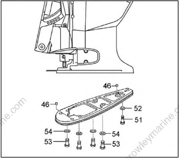
- A ¾" thick black anodized plate is provided to adapt the outboard mid-section to accept the jet drive. Install the two locating dowel pins and place the adapter in position on the mid section. Secure the adapter to the mid section from underneath with the four M10 x 35mm bolts and lock washers and with the single M8 x 30mm bolt and lock washer at the rear.
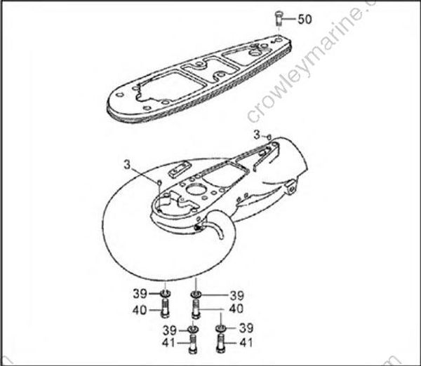
- Next, attach the jet-drive unit to the motor. Position two 3/16" x 1/2" dowel pins on the jet unit and grease the drive shaft splines and water tube grommet. Use two 5/16-18" x 2-1/2" bolts (40) in the forward holes and two 5/16-18" x 2-3/4" bolts (41) in the rear from underneath and one 3/8-16" x 1-1/2" bolt from above using the hole normally used for a trim tab. Coat all the bolt threads with grease and use the appropriate lock washers. Tighten all five bolts securely.
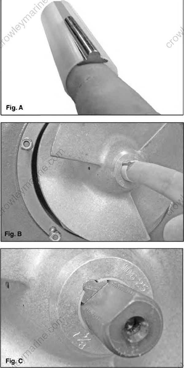
- Locate the impeller and retrieve the plastic sleeve and key from inside the hub. A spare sleeve and key should be present. Place one of each inside the owners’ packet to be given to the consumer upon retail sell. Apply marine grease to the shaft, inside the impeller hub and the retaining nut threads. Hold the plastic sleeve with the slit facing up while sliding the key inside it with the flat surface down and the rounded face protruding from the slit. Hold them in this position with your forefinger (Fig. A) and insert the pair into the impeller hub (Fig. B). Now, slide the impeller onto the shaft with the key oriented to the flat of the shaft (Fig. C).
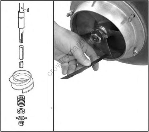
- Install the seven shim washers, nut retainer and nut but only slightly snug the nut. Check the impeller clearance by installing the intake liner and securing it with two nuts and washers without the grate. The washers will bridge the gap with the grate removed and allow the nuts to clamp the liner. Using a feeler gauge, check the clearance between each blade and the liner. There will be some variance from one to the other, but you are only concerned with the closest blade. If the tightest tolerance is more than 0.032", one shim should be moved to the top of the impeller and the tolerance remeasured. This should be rare for a new unit but may be common on those with some time. Sand and gravel will wear the impeller and liner during operation.
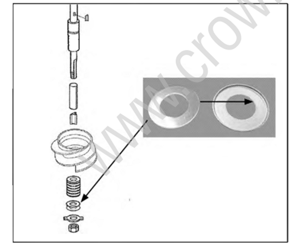
Now that the impeller has the proper tolerance, remove the nut and nut retainer to install the torsion damper. Position one urethane washer in the concave side of the cup, the other should be placed with the Owner's Manual. Install the cup on the impeller shaft with the urethane washer against the last shim washer. Never position the urethane washer against the hub, drive shaft sleeve or the nut keeper.
Reinstall the nut retainer and nut. Tighten the nut by bumping the wrench slightly to rotate the nut until the ears of the retainer can be folded down over a flat on the nut. If an ear cannot be folded down on a flat, remove the nut and flip the retainer over and try again.
Position the intake onto the drive with the lower end at the rear. Secure it with the lock nuts provided in place after coating the threads of the studs with grease.
Attach the shift cable anchor bracket to the jet drive, screw the ball end all the way onto the shift cable, then tighten the jam nut. Attach the shift cable to the cable support bracket on the jet drive with the U-clamp centered in the cable recess. Twist the cable in the U-clamp so the cable rests against the motor cowling and tighten the clamp screws. The clamp base is slotted to allow alignment for minimum cable bending.
Place the shift handle in forward, solidly in the detent. The reverse gate cam roller must be at the rear end of the cam slot. If these conditions are not met, slide the cable anchor bracket on the jet drive and/or adjust the threaded rod end on the cable. The cable end must be screwed in at least 8mm (0.31").
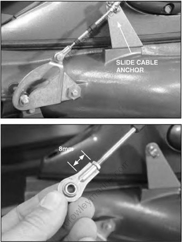
Shift to reverse and back to forward. Do not be concerned if the gate does not completely reach reverse. There is clearance at this position and water pressure will close the gate.
In forward, with the roller at the rear end of the cam slot, the gate should not rotate toward reverse if lightly forced. Pull on the gate by hand to verify this. If further adjustments are required, see the Maintenance, Lubrication, and Storage section of this manual.
Lock the nuts on the cable against the rod ends to complete the adjustment.
