

Step 1: OUTBOARD INSTALLATION
Attach chain to lift eye on back of engine block.
If the chain snap hooks are too large, the cast in lift eye could break causing the outboard to drop suddenly causing personal injury and damaging the outboard.
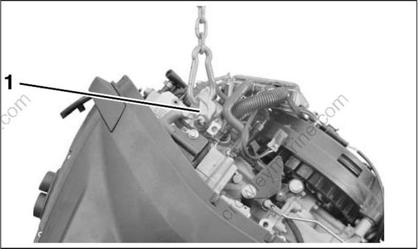
- Lift eye
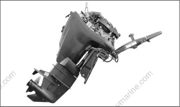
Carefully lift engine with hoist.
To avoid damage to the outboard, lift the outboard in one smooth motion. DO NOT allow the outboard to bounce.
Step 2: STEERING SYSTEMS
Mechanical Cables
All Evinrude outboards equipped with tilt tubes are compatible with mechanical steering systems that meet ABYC Standard P-17. Single-cable mechanical steering systems can be used on single or dual-outboard installations if an ABYC-approved steering link is used. Dual-cable mechanical steering helps provide firm steering control at high speeds.
Dual-cable mechanical steering helps provide firm steering control at high speeds.
Extend the steering cable and lubricate the inner core before installation.
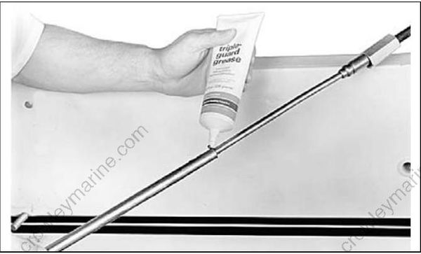
ABYC-approved mechanical steering cable.
IMPORTANT: Install steering cable through tilt tube before mounting outboard on transom. Tighten nut securely.
DO NOT use cable over pulley steering on 40 HP and larger outboards.
Manual Hydraulic Steering
Manual hydraulic steering systems use hydraulic fluid to transfer motion and load from the helm to the outboard.
Use only a hydraulic steering system designed for the specific application. Refer to the steering system manufacturer’s specifications for recommended applications.
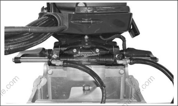
Typical manual hydraulic steering
IMPORTANT: Some hydraulic steering systems require additional centerline spacing in dual-outboard installations. Refer to steering system manufacturer’s recommendations and to Dual-Outboard Centerlines on p. 33.
Drag Links
Use the correct drag link to allow full steering travel:
| Model | Drag Link |
|---|---|
| 90° V6 | P/N175125 |
| 60° V4–V6 | P/N175125 |
| 75–90 HP | P/N175125 |
| 40–60 HP | P/N173699 |
| 15–30 HP | P/N173699 |
Install cable wiper nut on tilt tube and connect drag link to the correct location on the steering arm. For single motor, single cable applications, the drag link should be installed in the rear hole.
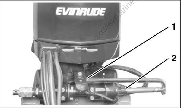
- Drag link connection
- Wiper nut
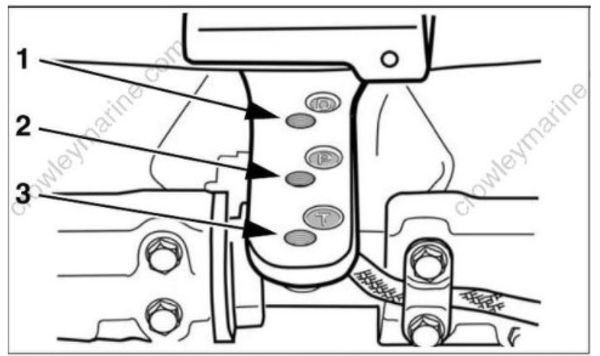
- Rear Location (D)–Steering drag link connection
- Middle Location (P)–Power steering connection (Refer to manufacturer’s instructions for hydraulic steering systems.)
- Front Location (T)–Bar connection (multiple outboard installations)
