

Cable and Hose Installation
Before installation, identify all required wiring, cables, and hoses:
• Throttle and shift cables
• Instrument harnesses
• Battery cables and switches
• Oil tank sender harness
• Fuel supply hose
• Primer bulb or primer pump
• Oil supply hose.
Determine whether any additional wiring or hoses will be needed for accessory gauges or batteries:
• Speedometer pick-up hose
• Mechanical water pressure gauge hose
• Accessory battery charging kit
• I-Command adapter harnesses
• I-Command water pressure sensor kit
• I-Command oil level sensor kit.
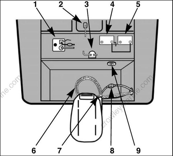
DRC6487
Typical outboard installation
- Oil tank
- Anti-siphon valve
- Water separating fuel filter
- Starting battery
- Accessory battery
- Flexweave protective sleeve
- Access cover
- Primer bulb
- Battery switch
Boat Cable and Harness Routing
Improper installation and routing of outboard controls could wear, bind, and damage components, causing loss of control.
Remote control cables, wiring, and hoses must follow a similar path into the lower motor covers. Select the best routing for the specific application.
All cables, wiring, and hoses must be long enough to provide adequate slack. Check clearances at all possible combinations of trim angles and steering positions.
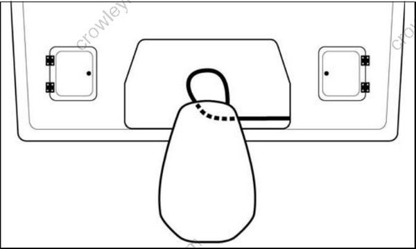
DRC7799
Typical Small Splash Well
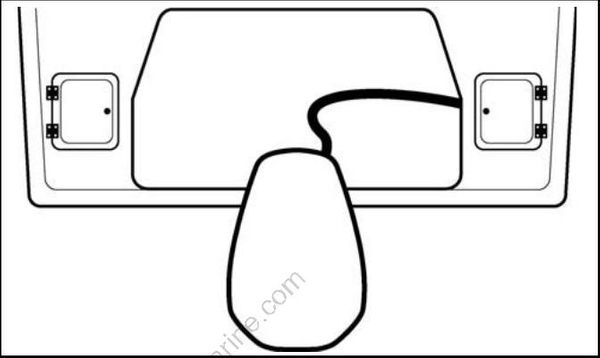
DRC7797
Typical Large Splash Well
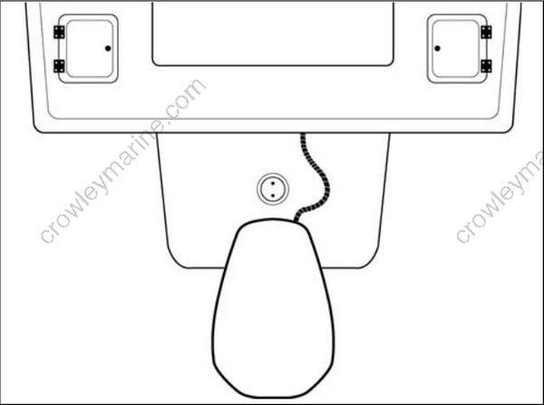
DRC7798A
Typical Engine Bracket
Protective Sleeve/Conduit
Make sure all cables, wiring, and hoses have been identified and fitted to the appropriate lengths. Refer to OUTBOARD RIGGING on p. 51.
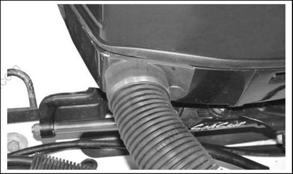
Next, bundle the components that route to the outboard with appropriate shielding, such as an expandable “flexweave” sleeve or a flexible conduit.
005138
Flexible conduit installation
Battery Cables
When routing battery cables, be sure to:
• Route cables through the protective sleeve.
• Use the most direct path to route the battery cables to the battery or battery switch.
Fuel Hose
The fuel hose may be routed outside of the protective sleeve or conduit. Electric primers or manual primers may not require this consideration.
Route fuel hoses with enough slack to allow the primer bulb arrow to point “up” during use.
Install the primer bulb with the arrow pointing in the direction of fuel flow to the outboard.
Connect the fuel supply hose from the fuel tank to the fuel supply line at the outboard.
IMPORTANT: Do not permanently fasten this connection until the boat's fuel system has been primed.
Oil Supply Hose
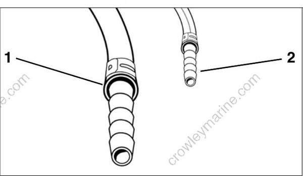
Evinrude E-TEC V4–V6 outboards use a single oil supply hose connected to the outboard and to the boat-mounted oil tank.
• Route the hose from the oil tank to the ¼ in. (6.4 mm) fitting of the oil supply line at the lower motor cover.
• Install the hose on the fitting using the proper size Oetiker† clamp.
003963
- Fuel supply hose and fuel fitting - 3/8 in. (9 mm)
- Oil supply hose and fitting - 1/4 in. (6 mm)
Oetiker Clamp Servicing
Clamp Identification
Use Oetiker clamps for making hose connections. These clamps provide corrosion resistance, minimize the potential for abrasion of rigging components, and provide solid, permanent connections.
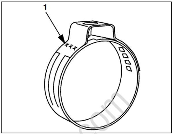
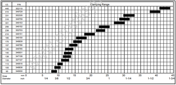
The selection and installation of an Oetiker clamp is essential in the proper sealing of hose connections. The clamp identification numbers appear on the side of the clamp, near the top of the ear. Refer to Clamp Selection chart for dimensions.
DO NOT re-use Oetiker clamps. Fuel leakage could contribute to a fire or explosion.
000093
- Clamp identification numbers
Clamp Selection
To select the correct size Oetiker clamp, measure the outside diameter of the hose when installed on the fitting.
Chose a clamp so that the outside diameter of the hose is approximately in the middle of the clamping range of the clamp.
008458
Clamp Installation
A constant stress should be applied to close the ear clamps. This method ensures a positive stress on the hose and does not result in excessive compression or expansion of the band material.
IMPORTANT: Use only Oetiker recommended
tools to close Oetiker stepless clamps.
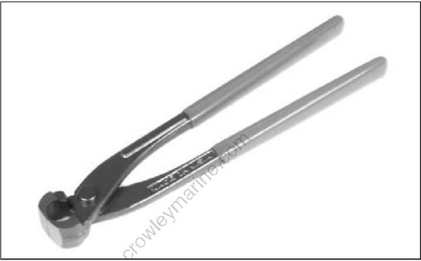
Oetiker pincers are available in the Evinrude/ Johnson Genuine Parts and Accessories Catalog
DP0886
• Position correct size clamp over hose.
• Install hose on fitting.
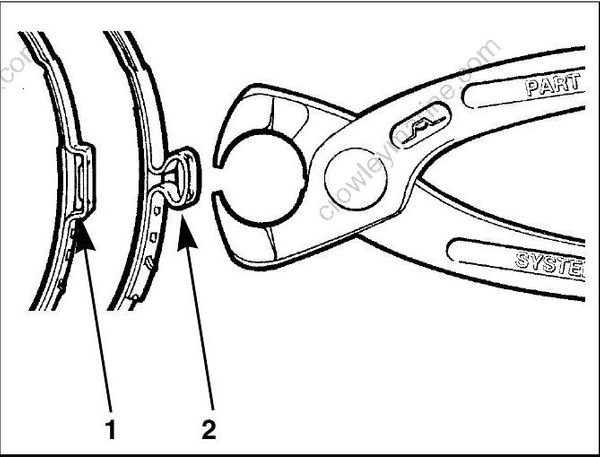
• Close clamp ear fully with Oetiker pincers (pliers).
000092
- Open clamp
- Closed clamp
Clamp Removal
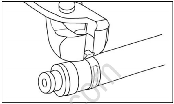
Method 1: Position Oetiker pincers across clamp ear and cut clamp.
000108
Method 2: Lift end of stepless clamp with screwdriver.

000090
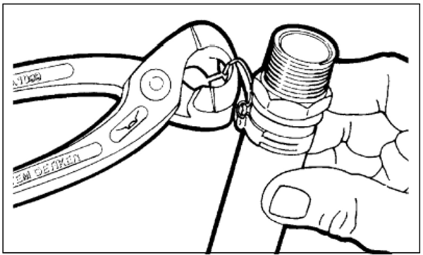
Method 3: Use Oetiker pincers (pliers) to grip clamp. Pull clamp off of connection and discard.
000091
