

Control Cable Identification
IMPORTANT: Identify control cable function before rigging outboard.
Identify each control cable:
• Put the control handle into NEUTRAL position. The throttle cable casing guide will retract completely and the shift cable casing guide will go to the midpoint of its travel.
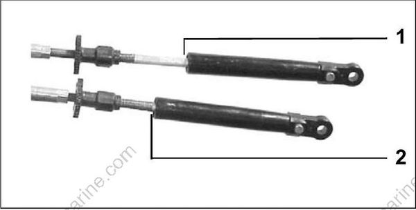
DP0811
- Shift cable casing guide extended to midpoint
- Throttle cable casing guide retracted
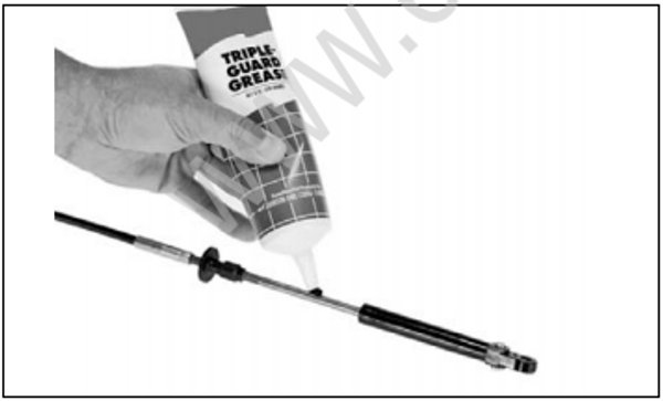
Extend the control cables and lubricate them with Triple-Guard grease.
Cable Retainer Clip Installation
When installing retainer clips on control arm linkage pins, clips should be locked and must not be bent or deformed.
For proper installation, review the following steps:
• Place washer on pin.
• Position retainer clip with straight section on the bottom and angled section on the top.
• Use long nose pliers to insert straight section of clip into linkage pin hole.
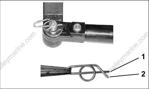
DP0818N / DP0817
- Straight section
- Angled section
• Push the clip towards the hole while lifting on the curved end with the pliers.
• Be sure retainer clip fully engages the pin.
• Lock the retainer by moving the angled section behind the straight section.
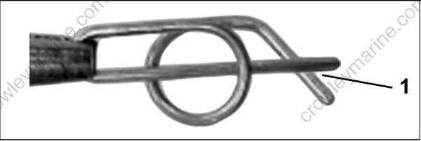
DP0817A
Locked Retainer Clip
