

EXPLODED DIAGRAM
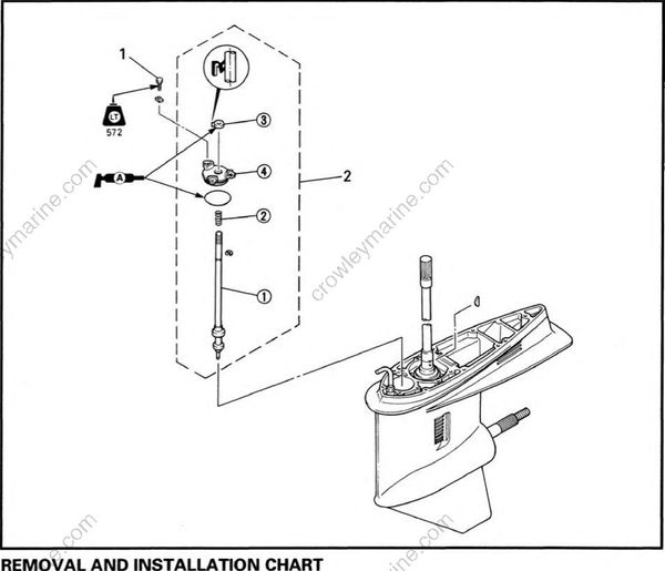
REMOVAL AND INSTALLATION CHART
| Step | Procedure/Part name | Q'ty | Service points |
|---|---|---|---|
| SHIFT ROD REMOVAL | Follow the left "Step" for removal | ||
| Impeller plate | Refer to "WATER PUMP" Section | ||
| 1 | Bolt (with washer) | 3 | |
| 2 | Shift rod assembly | 1 | NOTE: Remove the shift rod When shift actuator is in neutral |
| SHIFT ROD DISASSEMBLY | |||
| (1) | Shift rod | 1 | |
| (2) | Spring | 1 | |
| (3) | Oil seal | 1 | |
| (4) | Oil seal housing | 1 | |
| Reverse the removal steps for installation. |
