

POWER TRIM AND TILT ASSEMBLY
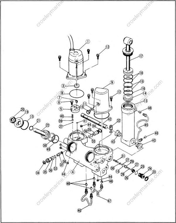
The trim and tilt assembly has many similar types of parts.
When assembling, be careful that all parts are reinstalled correctly in their positions.
The following diagram shows the springs, O-rings, steel balls, etc. When reassembling, refer to the diagram so they are not confused.
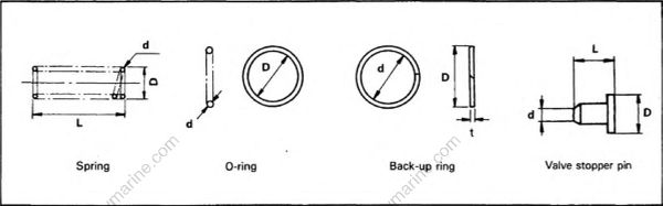
| D | d | t | L | |||
|---|---|---|---|---|---|---|
| • | Power trim and tilt assembly | 1 | ||||
| 1 | Motor assembly | 1 | ||||
| 2 | Oil seal | 1 | ||||
| 3 | O-ring | 2 | ||||
| 4 | Trim and tilt housing | 1 | ||||
| 5 | Gear pump assembly | 1 | ||||
| 6 | Socket head bolt | 3 | ||||
| 7 | Connecter shaft | 1 | ||||
| 8 | O-ring | 2 | 70.5 | 2 | ||
| 9 | Reservoir body | 1 | ||||
| 10 | Reservoir plug | 1 | ||||
| 11 | O-ring | 2 | 8.8 | 1.9 | ||
| 12 | Screw with washer | 6 | ||||
| 13 | Tilt cylinder | 1 | ||||
| 14 | Free piston | 1 | ||||
| 15 | O-ring | 4 | 38.7 | 3.5 | ||
| 16 | Back-up ring | 2 | 45 | 39 | 1.25 | |
| 17 | Tilt piston sub-assembly | 1 | ||||
| 18 | O-ring | 1 | 44.7 | 2.4 | ||
| 19 | Trim cylinder end screw | 2 | ||||
| 20 | Dust seal | 2 | ||||
| 21 | O-ring | 2 | 15.8 | 2.4 | ||
| 22 | Trim piston sub-assembly | 2 | ||||
| 23 | Snap ring | 1 | ||||
| 24 | Manual release screw | 1 | ||||
| 25 | O-ring | 1 | 16.8 | 1.9 | ||
| 26 | Manual valve seat screw | 1 | ||||
| 27 | Ball | 3 | 5/32 in (3.97 mm) | 5/32 in (3.97 mm) | ||
| 28 | Manual release rod | 1 | ||||
| 29 | Manual valve seat | 1 | ||||
| 30 | Manual release pin | 2 | 8.8 | 4.9 | 7.5 | |
| 31 | Manual release spring | 1 | 8.8 | 1.8 | 36.8 | |
| 32 | Up-release valve sub assembly | 1 | ||||
| 33 | O-ring | 2 | 13 | 1.9 | ||
| 34 | Snap ring | 2 | ||||
| 35 | Main valve sub-assembly | 2 | ||||
| 36 | O-ring | 2 | 14.8 | 1.9 | ||
| 37 | Shuttle piston | 1 | ||||
| 38 | Back-up ring | 1 | 12 | 9 | 1 | |
| 39 | Valve support pin | 1 | 5.6 | 3.5 | 7.0 | |
| 40 | Down-relief spring | 1 | 5.8 | 0.8 | 20.5 | |
| 41 | O-ring | 1 | 5.8 | 1.9 | ||
| 42 | Lower shock mount pin | 1 | ||||
| 43 | Bushing | 2 | ||||
| 44 | Taper screw plug | 5 | ||||
| 45 | Pipe 3 | 1 | ||||
| 46 | Pipe 1 | 1 | ||||
| 47 | Pipe 2 | 1 | ||||
| 48 | Union seat | 6 | ||||
| 49 | O-ring | 2 | 32.7 | 3.5 | ||
| 50 | Back-up ring | 2 | 39 | 33 | 1.25 |
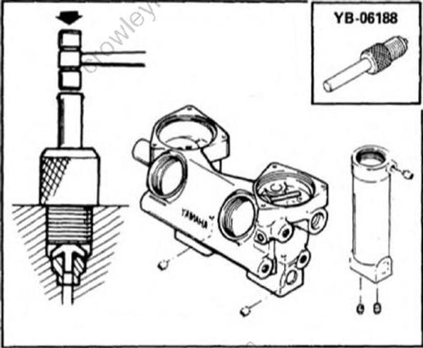
1. Trim and tilt housing
- By screwing in the union seat, installer, force-fit the union seat.
Always use a new union seat when reassembling; otherwise, pressure leakage will result.
- Using the socket wrench (5MM Allen) and bit socket (5MM Allen), screw in five taper screw plugs.
TIGHTENING TORQUE : 12 Nm (1.2 m•kg, 8.7 ft•lb)
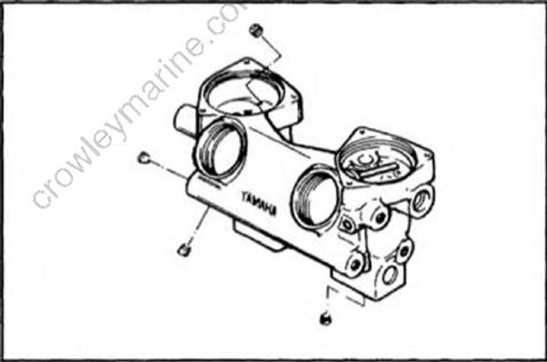
Install the trim and tilt housing onto the vise.
Install the tilt cylinder and connect the three pipes to the cylinder.
Union nut tightening torque.
TIGHTENING TORQUE : 19 Nm (1.9 m•kg, 13 ft•lb)
1. Tighten the union nuts alternately and in steps when connecting the pipe.
2. Be careful that pipe A and B are not confused.
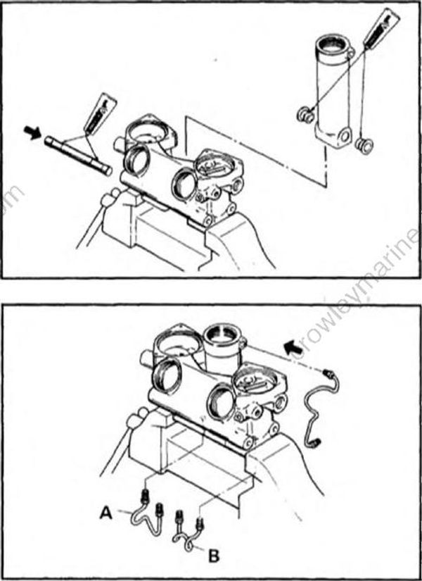
2. Tilt piston
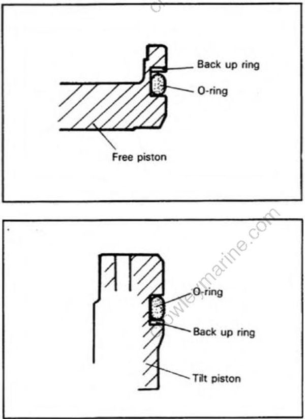
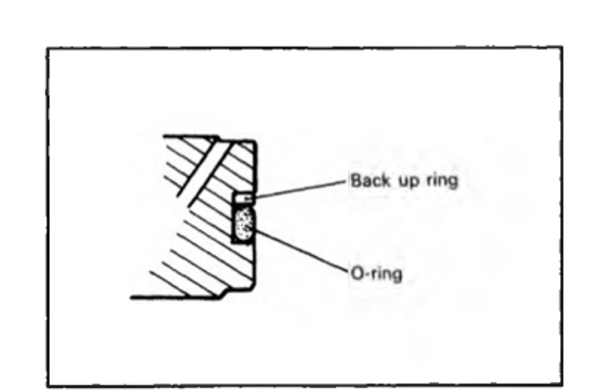
- Install the O-ring and back-up ring on to the free piston.
- Install the O-ring and back-up ring on to the tilt piston.
• The back-up ring protects the O-ring from deformation caused by variations in pressure.
• The back-up ring should be installed on the side where pressure is lower.
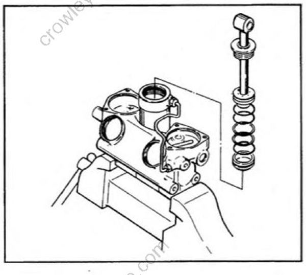
- Install the free piston and tilt piston sub-assembly in the tilt cylinder, and using the cylinder end screw wrench, tighten it to specification.
TIGHTENING TORQUE : 85 N m (8.5 m•kg, 61 ft•lb)
3. Trim piston
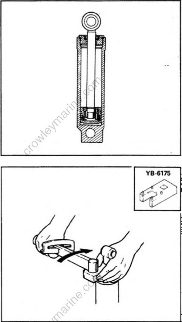
- Install the O-ring and back-up ring on to the trim piston sub-assembly.
Note the back-up ring position.
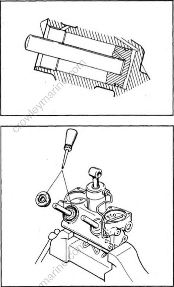
- Install the trim piston in the cylinder.
1. Be careful that the O-ring is not cut by threads of the cylinder end screw.
2. Insert it straight into the cylinder.
- Install the dust seal and O-ring onto the cylinder end screw, and screw it into the trim cylinder.
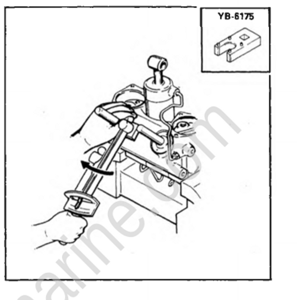
- Using the cylinder screw wrench, tighten the cylinder end screw.
While holding the special tool, tighten the screw slowly.
TIGHTENING TORQUE : 85 Nm (8.5 m•kg, 61 ft•lb)
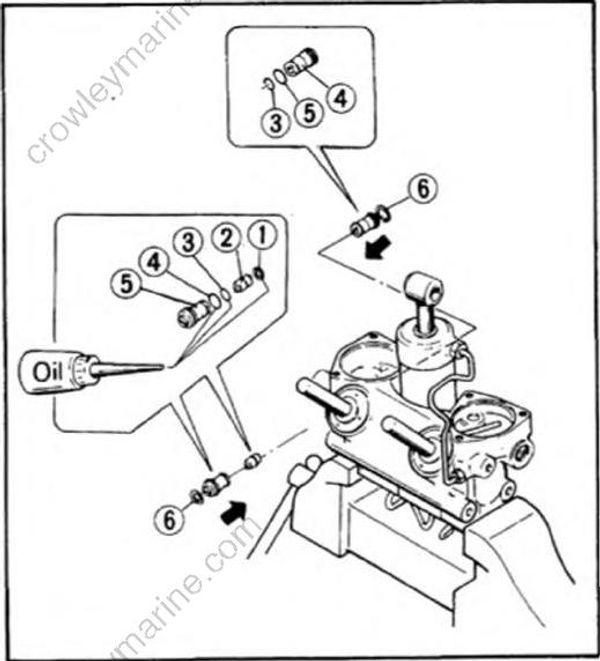
4. Manual valve
Install the manual valve in the trim and tilt housing. Using the driver, tighten the manual valve seat screw to specification.
Manual valve seat screw tightening torque : 13 Nm (1.3 m•kg, 9.4 ft•lb)
1. Position the manual release screw with the manual valve side facing upward so that the steel balls don't roll back and forth.
2. For easy operation, use of tweezers is recommended.
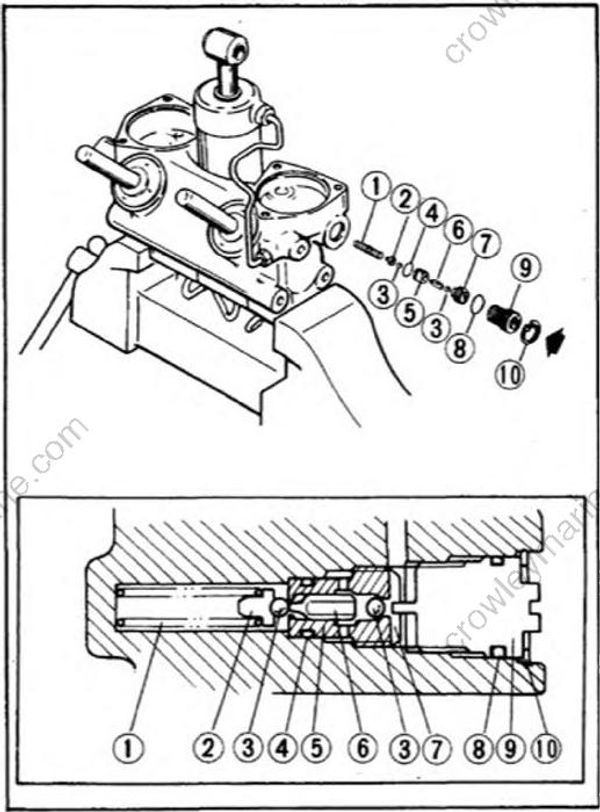
- Manual release spring
- Valve support pin
- Ball
- O-ring
- Manual valve seal
- Manual release rod
- Manual release screw
- O-ring
- Manual release screw
- Snap ring
5. Main valve
Place the main valve in the trim and tilt housing, and lock it with the circlip. Insert the shuttle piston from the other side and install the main valve.
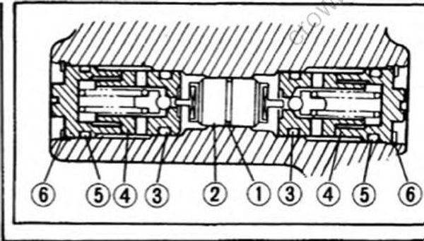
- Back-up ring
- Shuttle piston
- O-ring
- Main valve sub-assembly
- O-ring
- Snap ring
• Oil the parts before installing.
• Hydraulic oil should be used.
• Insert the shuttle pin straightly.
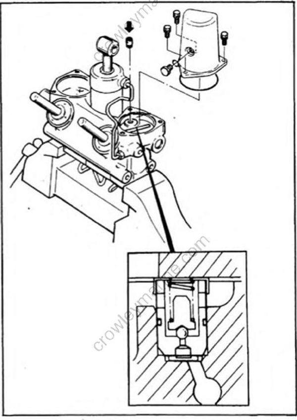
6. Up-relief valve
Fit the up-relief valve into the reservoir side by forcing it by hand, and secure the reservoir with three bolts.
Screw with washer tightening torque : 6 Nm (0.6 m•kg, 4.3 ft•lb)
7. Gear pump
Install the down-relief valve and the O-ring on the gear pump side, and secure the gear pump with the three socket head bolts.
Install the connector shaft onto the gear pump.
Socket head bolt tightening torque : 7 Nm (0.7 m•kg, 5.1 ft•lb)
1. When installing the gear pump assembly (5), hold the down-relief spring (3) in a vertical position.
2. The socket-head bolts (6) should be tightened alternately and in steps.
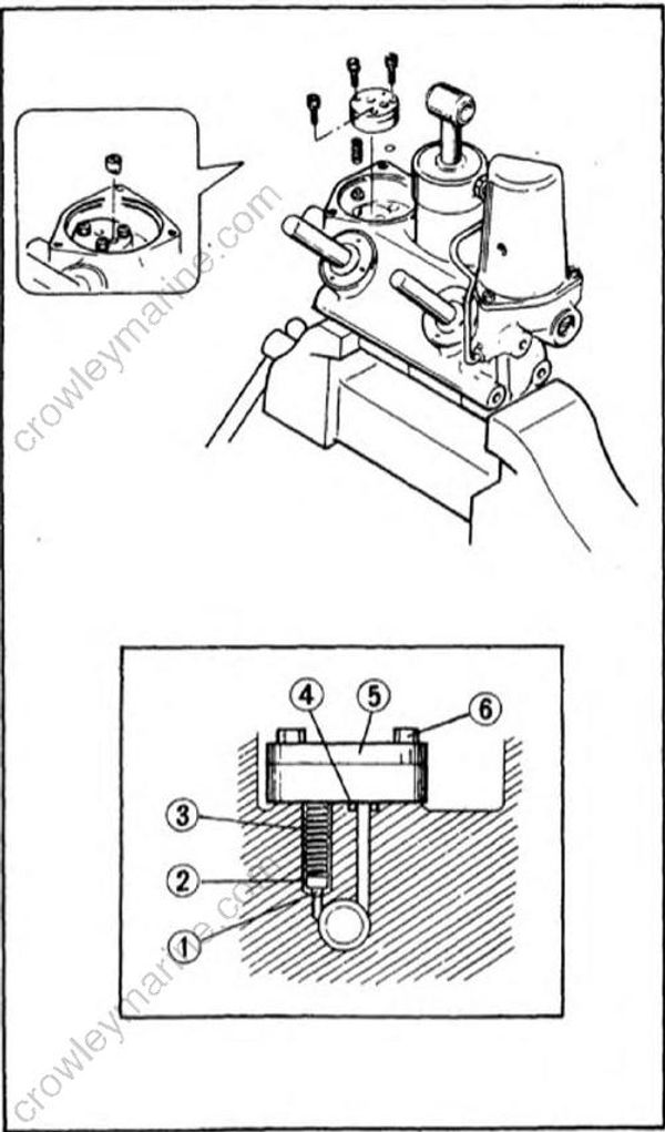
- Ball
- Valve support pin
- Down relief spring
- O-ring
- Gear pump assembly
- Socket-head bolt
8. Installing the motor
Install the connector shaft in the gear pump.
Screw with washer tightening torque : 6 Nm (0.6 m•kg, 4.3 ft•lb)
After installing the connector shaft, check that the gear pump assembly moves smoothly by turning the shaft.
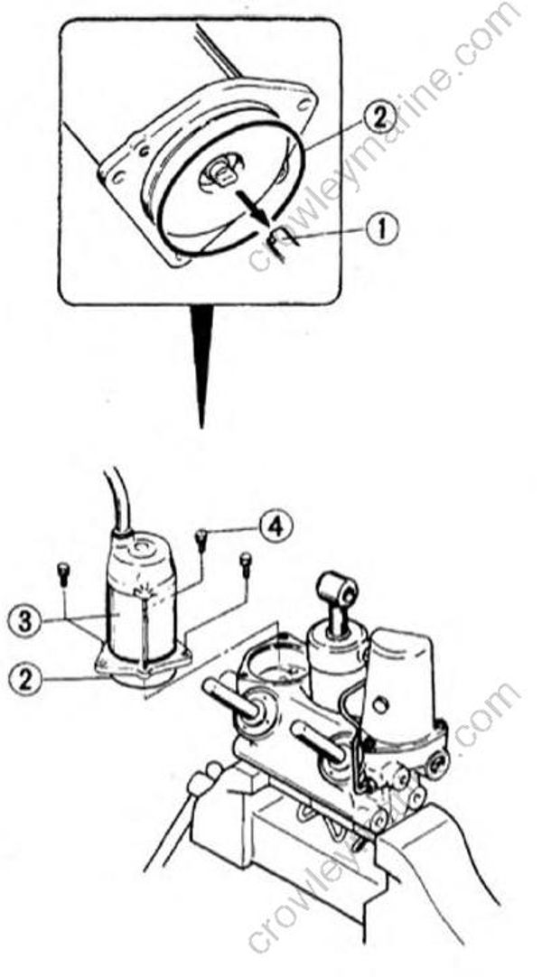
- Connector shaft
- O-ring
- Motor assembly
- Screw with washer
