

EXPLODED DIAGRAM
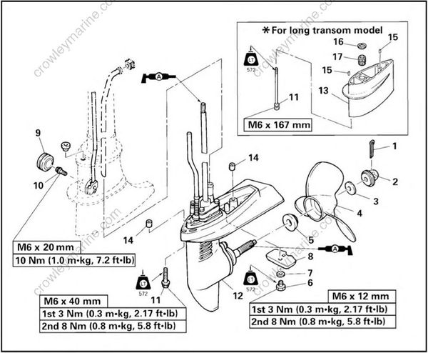
REMOVAL AND INSTALLATION CHART
| Step | Procedure/Part name | Q'ty | Service points |
|---|---|---|---|
| LOWER UNIT REMOVAL | Follow the left "Step" for removal. | ||
| 1 | Cotter pin | 1 | Not reusable |
| 2 | Propeller nut | 1 | |
| 3 | Washer | 1 | |
| 4 | Propeller | 1 | |
| 5 | Spacer | 1 | |
| 6 | Bolt (anode) | 1 | |
| 7 | Toothed washer (anode) | 1 | |
| 8 | Anode | 1 | |
| 9 | Grommet | 1 | |
| 10 | Bolt (shift rod connector) | 1 | NOTE: Set the shift lever to reverse position, and loosen the bolt (shift rod connector). |
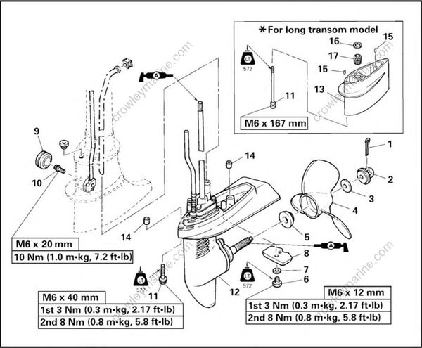
| Step | Procedure/Part name | Q'ty | Service points |
|---|---|---|---|
| 11 | Bolt with washer (lower unit) | 2 | For S-transom model |
| *For L-transom model | |||
| NOTE: When removing, screw out the bolt (rear) from upper case and remove the lower unit with extension. |
|||
| 12 | Lower unit ass'y | 1 | |
| 13 | Lower unit with extension | 1 | For L-transom model |
| 14 | Dowel pins | 2 | |
| 15 | Dowel pins | 2 | For L-transom mode |
| 16 | Circlip | 1 | |
| 17 | Bushing | 1 | |
| Reverse the removal steps for installation. |
SERVICE POINTS
Lower unit removal
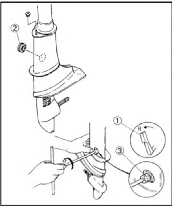
NOTE:
- It is possible to remove the Lower unit from the upper case without removing the power unit.
- Set the shift lever (1) to "REVERSE" position, then remove and install the lower unit.
- Remove:
- Grommet (2)
- Loosen:
- Bolt (3) (shift rod connector)
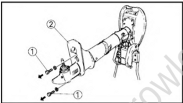
- Remove:
Bolt (1) (lower unit)
Lower unit (2)
NOTE:
For long transom model:
- When removing, screw out the bolt (rear) from upper case and remove the lower unit with extension.
- When installing, hold the bolt (rear) in hole of the extension and install the lower unit with extension to the upper case.

Lower unit installation
- Tighten:
- Bolt (1) (shift rod connector)
NOTE:
Push down the tilt lock plate (2) until it contacts the stopper and locate the shift lever in "REVERSE" position. Then tighten the bolt (1).
