

Drive shaft and lower case (counter rotation model)
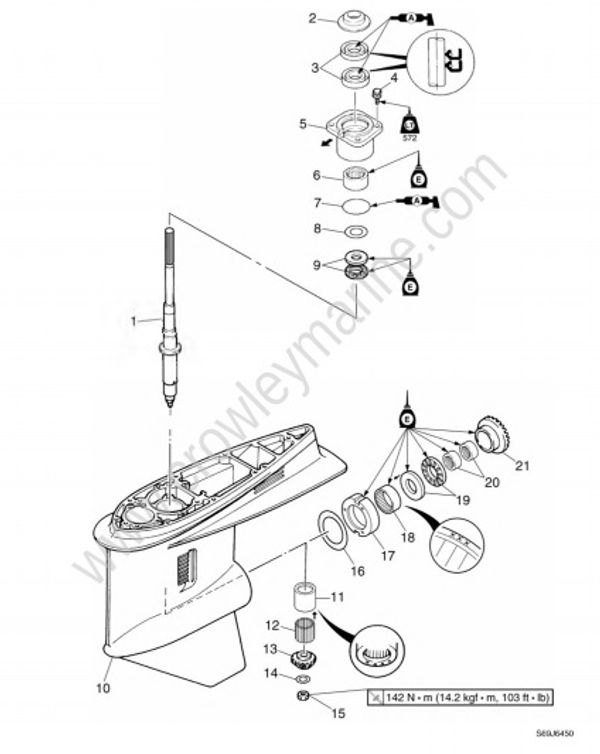
| No. | Part name | Q'ty | Remarks |
|---|---|---|---|
| 1 | Drive shaft | 1 | |
| 2 | Cover | 1 | |
| 3 | Oil seal | 2 | Not reusable |
| 4 | Bolt | 4 | M8 x 25 mm |
| 5 | Drive shaft housing | ||
| 6 | Needle bearing | 1 | |
| 7 | O-ring | 1 | Not reusable |
| 3x60.5 mm | |||
| 8 | Pinion shim | - | As required |
| 9 | Thrust bearing | 1 | |
| 10 | Lower case | 1 | |
| 11 | Needle bearing case | 24 | |
| 12 | Needle bearing | 1 | |
| 13 | Pinion | 1 | |
| 14 | Washer | 1 | |
| 15 | Nut | - | As required |
| 16 | Reverse gear shim | 1 | |
| 17 | Retainer | 1 | |
| 18 | Needle bearing | 1 | |
| 19 | Thrust bearing | 1 | |
| 20 | Needle bearing | 2 | Not reusable |
| 21 | Reverse gear | 1 |
Removing
Removing the drive shaft
- Remove the drive shaft assembly and pinion, and then pull out the reverse gear and thrust bearing.
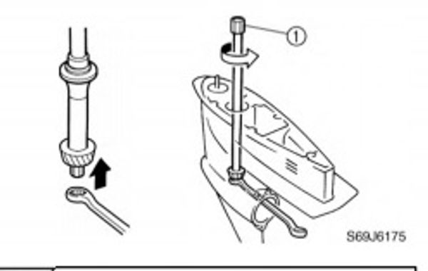
Drive shaft holder (1): YB-06201
Disassembling the drive shaft housing.
- Remove the cover, oil seals, and needle bearing.
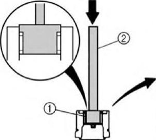
Drive shaft needle bearing remover and installer (1): YB-06196
Driver handle (2): YB-06071
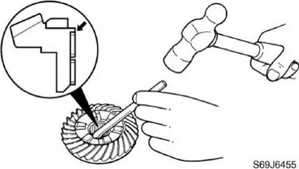
Disassembling the reverse gear
- Remove the needle bearing from the reverse gear using a chisel.
Disassembling the lower case
- Remove the retainer and shim(s).
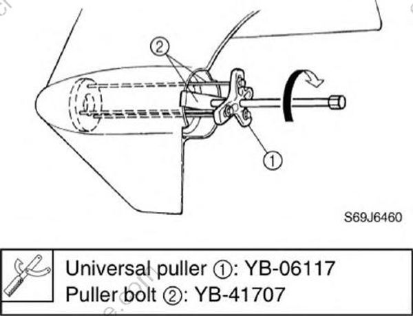
Universal puller (1): YB-06117
Puller bolt (2): YB-417-707
- Remove the needle bearing from the retainer.
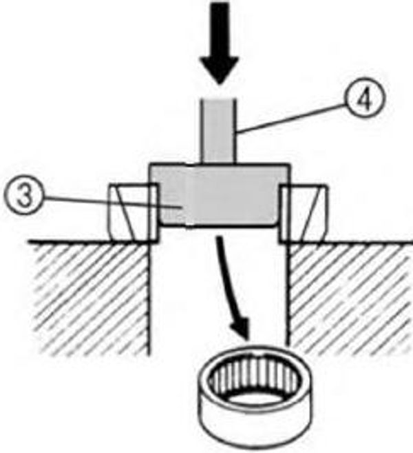
Needle bearing installer (3): YB-06434
Driver handle (4): YB-06071
- Remove the needle bearing.
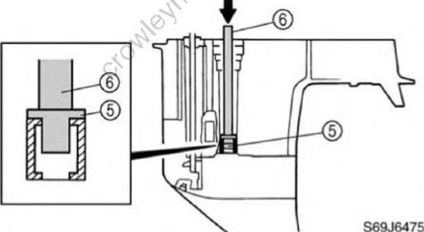
Roller bearing installer/remover (5):YB-06432
Driver handle (6): YB-06071
Checking
Checking the pinion and reverse gear
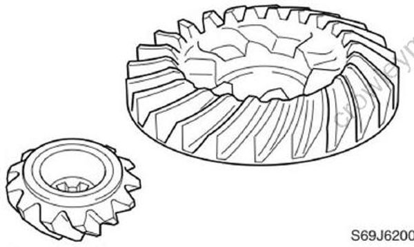
- Check the teeth of the pinion, and the teeth and dogs of the reverse gear for cracks or wear. Replace if necessary.
Checking the bearings
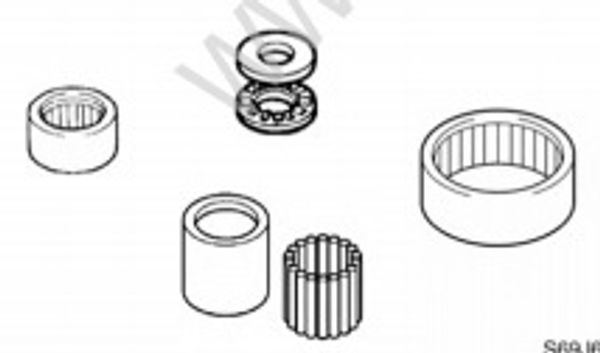
- Check the bearings for pitting or rumbling. Replace if necessary
Checking the drive shaft
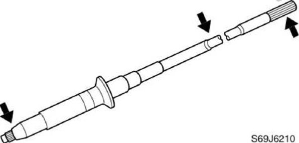
- Check the drive shaft for bends or wear.Replace if necessary.
Checking the lower case
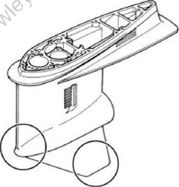
- Check the skeg and torpedo for cracks or damage. Replace if necessary.
Assembling
Assembling the lower case
- Install the needle bearing into the retainer to the specified depth.
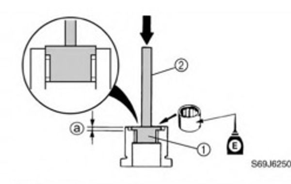
Needle bearing installer and remover(1): YB-06434
Driver handle (2): YB-06071
Depth (a):-0.25-0.25 mm (-0.010-0.010 in)
- Install the original shim(s) and retainer into the lower case.
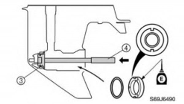
CAUTION:
Add or remove shim(s), if necessary,when replacing the forward gear or lower case.
Forward bearing installer (3): YB-06430
Driver handle (4): YB-06071
- Install the needle bearing outer case into the lower case.
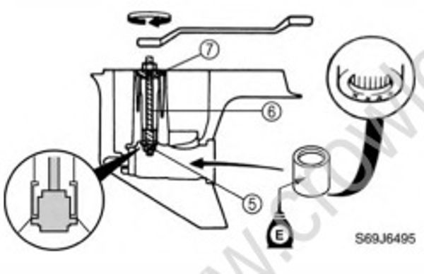
Note:
Apply engine oil to the needle bearing outer case before installation.
Needle bearing installer (5): YB-06435
Pinion gear bushing installer (6): YB-06029-4
Needle bearing remover and installer(7): YB-06213
- Install the needle bearing into the needle bearing outer case.
NOTE:
Apply engine oil or grease to the needle bearing, and then install it.
- Install the new needle bearings into the reverse gear to the specified depth.
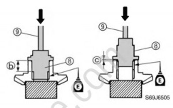
Needle bearing installer (8): YB-06435
Driver handle (9): YB-06071
Depth(b):20.75-21.25 mm (0.817-0.836 in)
Depth (C):4.25-4.75 mm (0.167-0.187 in)
- Install the thrust bearing and reverse gear into the lower case.
Assembling the drive shaft housing
- Install the needle bearing into the drive shaft housing to the specified depth.
Needle bearing installer and remover (1): YB_06194
Driver handle (2): YB-06071
Depth (a): 4.25-4.75 mm (0.167-0.187 in)
- Apply grease to the new oil seals, and then install them into the drive shaft housing to the specified depth.
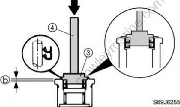
NOTE:
Install an oil seal halfway into the drive shaft housing, then the other oil seal.
Oil seal installer (3): YB-06195
Driver handle (4): YB-06071
Depth (b):0.25-0.75 mm (0.01-0.03 in)
Installing
Installing the drive shaft
- Install the forward gear to the lower case.
- Install the drive shaft housing (1), thrust bearing (2), and original shim(s) (3) to the drive shaft (4).
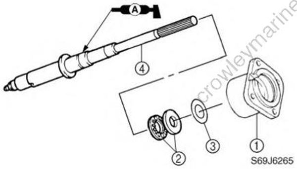
CAUTION:
Add or remove shim(s), if necessary,when replacing the drive shaft housing or drive shaft
- Install the drive shaft, housing, pinion,and pinion nut, and then tighten the nut to the specified torque.
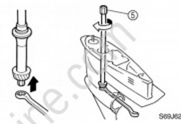
NOTE:
Install the drive shaft by lifting it up slightly,then aligning it with the pinion and the spline of the drive shaft.
Drive shaft holder (5): YB-06201
Pinion nut: 142 N m (14.2 kgf-m, 103 ft-lb)
- Tighten the housing bolts.
Installing the propeller shaft housing
- Install the propeller shaft housing assembly into the lower case.
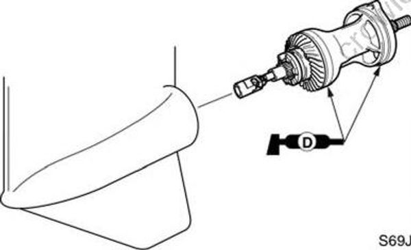
NOTE:
Apply grease to the new O-rings before installation.
- Install the bolts (1), ring (2),and bolts (3),and then tighten the bolts (1) to the specified torque.
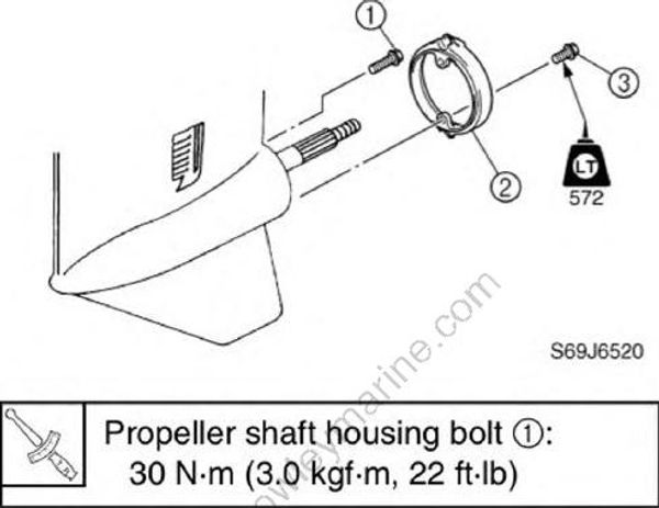
Propeller shaft housing bolt (1): 30 N-m (3.0 kgf-m, 22 ft-lb)
Installing the water pump and shift rod
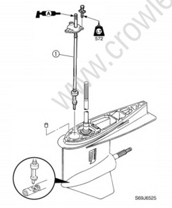
- Install the shift rod assembly (1).
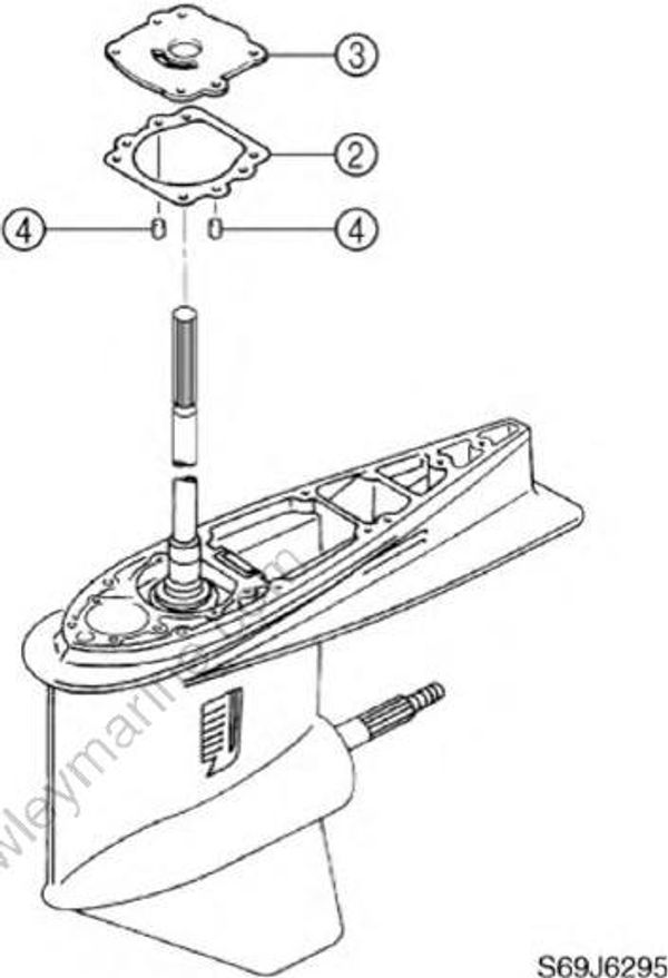
- Install the new gasket (2), outer plate cartridge (3), and dowel pins (4).
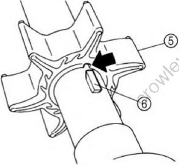
Install the Woodruff key into the drive shaft.
Align the groove on the impeller (5) with the Woodruff key (6), and then install it to the drive shaft.
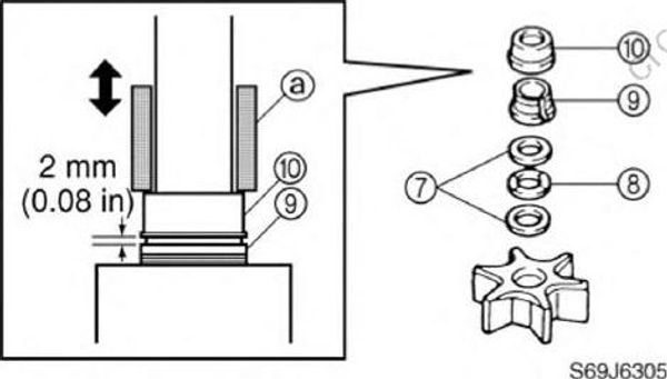
- Install the washers (7), wave washer (8),spacer (9), and collar (10) to the drive shaft.
NOTE:
- The collar and spacer should fit together firmly.
- While pulling the drive shaft up, install the collar with an appropriate tool (a) that fits over the drive shaft as shown.
- Install the O-ring (11) and insert cartridge (12) into the pump housing (13).
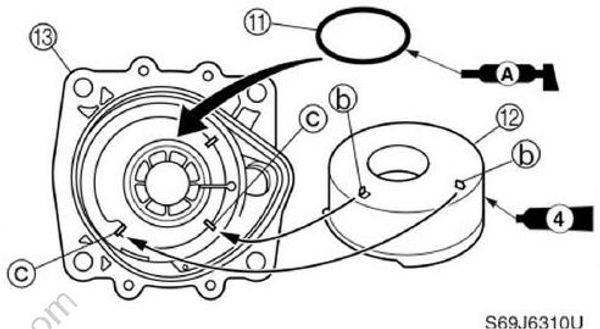
NOTE:
Align the insert cartridge projections (b) with the holes (c) in the pump housing.
- Install the O-ring (14) and pump housing assembly (15) into the lower case, tighten the bolts (16), and then install the seal (17) and cover (18).
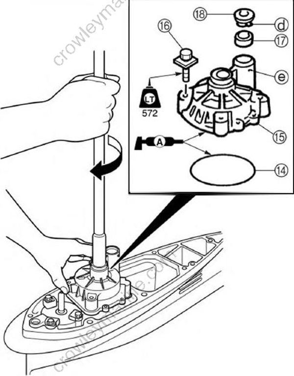
NOTE:
- When installing the pump housing, apply grease to the inside of the housing, and then turn the drive shaft clockwise while pushing down the pump housing.
- Align the cover projection (d) with the hole (e) in the pump housing.
Installing the lower unit
- Set the gearshift to the neutral position at the lower unit.
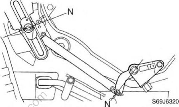
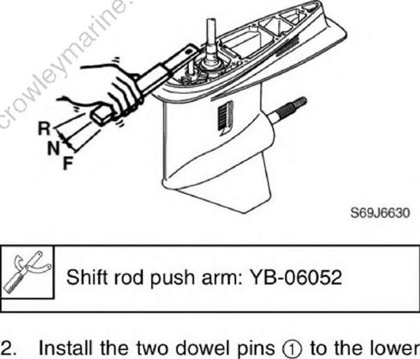
Shift rod push arm: YB-06052
Install the two dowels pins (1) to the lower unit.
Install the lower unit to the upper case,and then tighten the bolts (2) to the specified torque.
Install the trim tab (3) to its original position, and then tighten the bolt (4) to the specified torque.
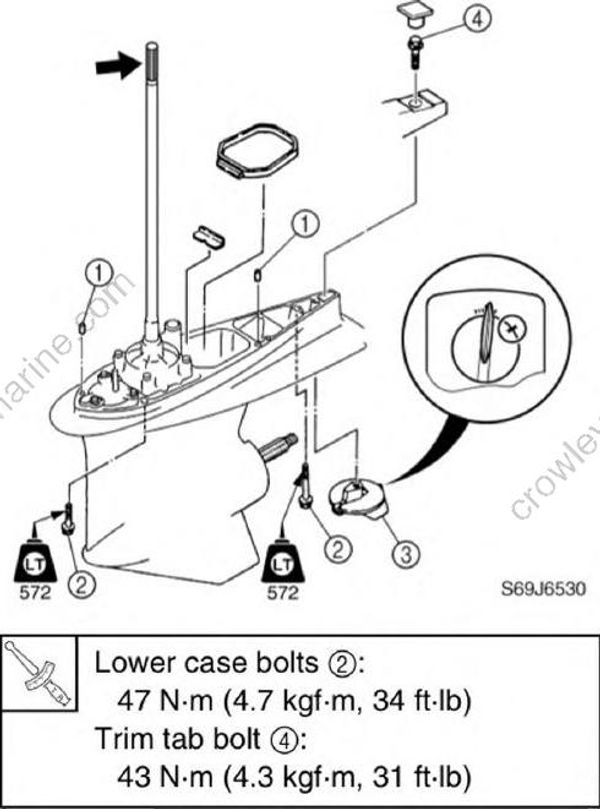
Lower case blolts (2): 47 N-m (4.7 kgf-m, 34 ft-lb)
Trim tab bolt (4): 43 N-m (4.3 kgf-m, 31 ft-lb)
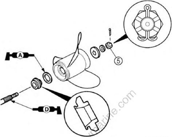
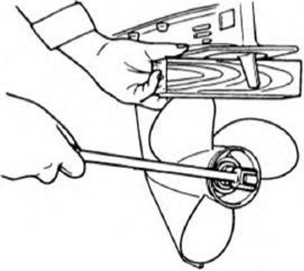
- Install the propeller and propeller nut,and then tighten the nut finger tight.Place a block of wood between the anti cavitation plate and propeller to keep the propeller from turning, and then tighten the nut to the specified torque
WARNING
Do not hold the propeller with your hands when loosening or tightening it. Be sure to disconnect the battery cables from the batteries and the engine stop lanyard switch. Put a block of wood between the anti-cavitation plate and propeller to keep the propeller from turning.
NOTE:
If the grooves in the propeller nut (5) do not align with the cotter pin hole, tighten the nut until they are aligned.
Propeller nut (5):55 N-m (5.5 kgf-m, 40 ft-lb)
