Drive shaft and lower case (F50B, F60B)

| No | Part name | Q’ty | Remarks |
|---|---|---|---|
| 1 | O-ring | 1 | Not reusable |
| 2 | Oil seal | 1 | Not reusable |
| 3 | Plate | 1 | |
| 4 | O-ring | 1 | Not reusable |
| 5 | E-clip | 1 | |
| 6 | Shift rod | 1 | |
| 7 | Drive shaft | 1 | |
| 8 | Taper roller bearing | 1 | Not reusable |
| 9 | Shim (T3) | - | |
| 10 | Sleeve | 1 | |
| 11 | Nut | 1 | |
| 12 | Water inlet cover (STBD) | 1 | |
| 13 | Lower case | 1 | |
| 14 | Water inlet cover (PORT) | 1 | |
| 15 | Screw | 1 | M5 x 25 mm |
| 16 | Shift cam | 1 | |
| 17 | Shim (T1) | - | |
| 18 | Taper roller bearing | 1 | Not reusable |
| 19 | Forward gear | 1 | |
| 20 | Needle bearing | 1 | Not reusable |
| 21 | Pinion | 1 | |
| 22 | Nut | 1 | M12 |
Removing the drive shaft
- Loosen the pinion nut, and then remove the pinion “1” and drive shaft “2”.

Drive shaft holder "3": YB-06049
Pinion nut holder "4": YB-06715
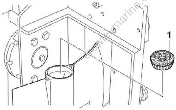
- Remove the forward gear assembly “1 ”
Removing the shift rod
- Remove the shift rod assembly “1” and shift cam “2”.

Disassembling the drive shaft
- Remove the taper roller bearing “1".
NOTICE
Do not press the threads “a” of the drive shaft directly.
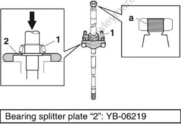
Bearing splitter plate"2": YB-06219
Disassembling the forward gear
- Remove the taper roller bearing “1 ”,
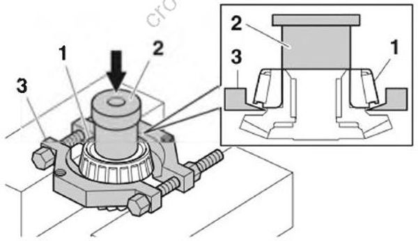
Driveshaft needle bearing installer and remover “2”: YB-06196
Bearing separator plate “3”: (commercially available)
- Remove the needle bearing from the reverse gear.
Disassembling the shift rod
- Remove the O-rings “1 ” and “2”, plate “3”, oil seal “4”, and E-clip “5
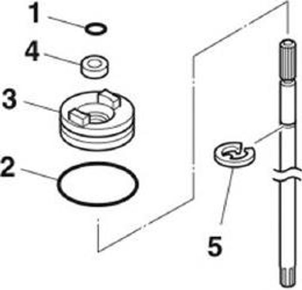
Disassembling the lower case
WARNING
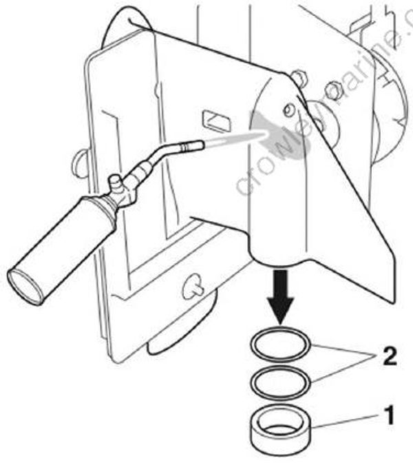
- Use heat-resistant gloves. Otherwise, burns could result.
- To prevent fires, remove any flammable substances, such as gasoline and oil,around the working area.
- Keep good ventilation while working.
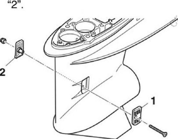
- Remove the water inlet covers “1” and "2".
- Heat the installation area of the taper roller bearing outer race in the lower case using a gas torch, and then remove the taper roller bearing outer race “1” and forward gear shims “2”.
NOTICE
When heating the lower case, heat the entire installation area evenly. Otherwise, the paint on the lower case could be burned.
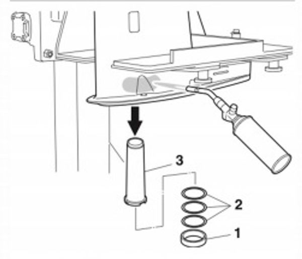
- Heat the installation area of the taper roller bearing outer race in the lower case using a gas torch, and then remove the taper roller bearing outer race “1”, pinion shims “2”, and sleeve “3”.
NOTICE
When heating the lower case, heat the entire installation area evenly. Otherwise, the paint on the lower case could be burned.
- Remove the needle bearing "1"
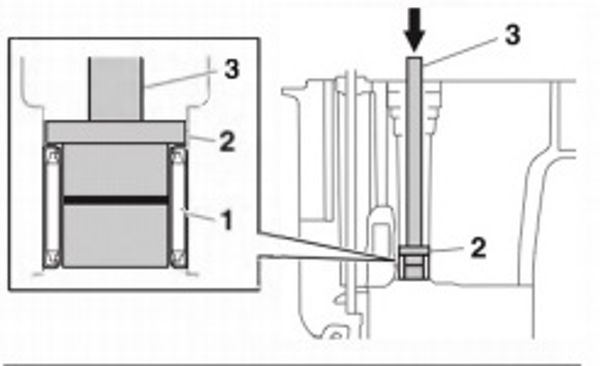
Propeller shaft needle bearing attachment “2”: YB-06063
Driver handle (large) “3”: YB-06071
Checking the pinion
Checking the forward gear
Checking the drive shaft
Check the drive shaft. Replace if damaged or worn.
Measure the drive shaft runout.
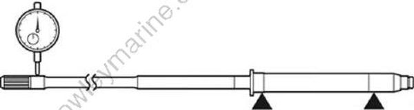
Drive shaft runout: 0.5 mm (0.0197 in)
Checking the lower case
Assembling the forward gear
- Install a new taper roller bearing “1”.
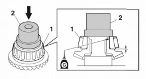
Roller bearing installer/remover “2”: YB-06432-1A
Assembling the drive shaft
- Install a new taper roller bearing “1”.
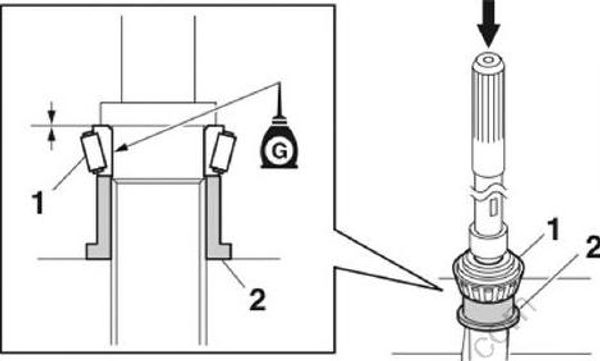
Bearing inner race attachment “2”: 90890-06644
Assembling the shift rod
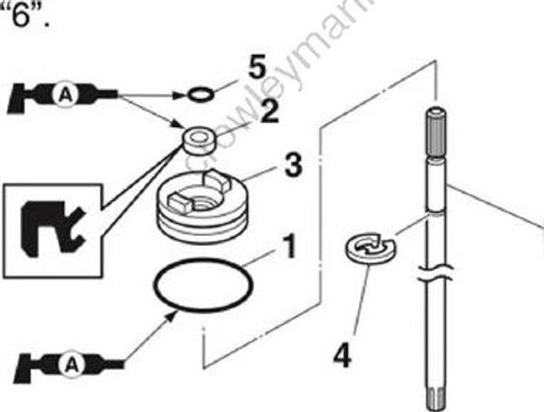
Install a new O-ring “1 ” and a new oil seal “2” to the plate “3”.
Install the E-clip “4”, the plate assembly “3”, and a new O-ring “5” to the shift rod "6".
Assembling the lower cas
Warning
- Use heat-resistant gloves. Otherwise, burns could result.
- To prevent fires, remove any flammable substances, such as gasoline and oil, around the working area.
- Keep good ventilation while working.
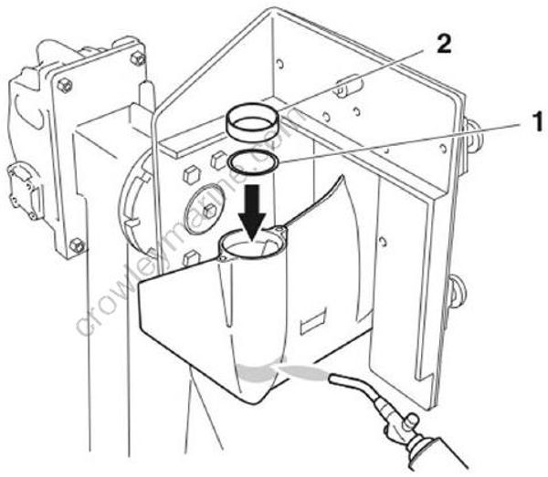
Install the original forward gear shims “1 ”,
Heat the installation area of the taper roller bearing outer race in the lower case using a gas torch, and then install a new taper roller bearing outer race “2”.
NOTICE
When heating the lower case, heat the entire installation area evenly. Otherwise, the paint on the lower case could be
burned.
TIP
Do not reuse a shim if deformed or scratched.
- While holding the special service tool “1”, strike the tool to check that the taper roller bearing outer race is installed properly.
TIP:
If a high-pitched metallic sound is produced when the special service tool is struck, the outer race is installed properly.
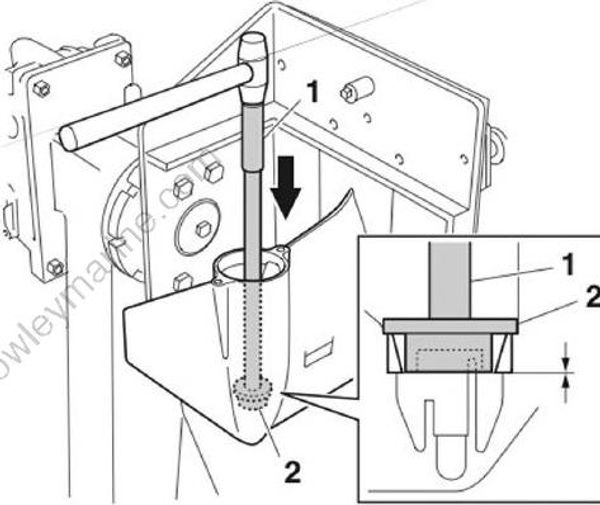
Driver handle (large) “1”: YB-06071
Forward gear bearing cup installer “2”: YB-41446
- Install a new needle bearing “1” into the lower case to the specified installation depth “a”.
TIP:
Face the bearing identification mark “b” on
the needle bearing up.Mark the driver handle at the specified installation depth “a” with an identification mark “c”, and then install the needle bearing to the specified installation depth.
Make sure to measure the depth on the driver handle from the flange bottom of the special service tool “3”.
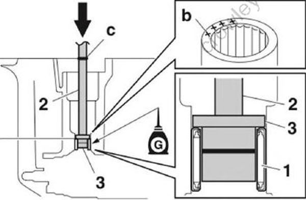
Driver handle (large) “2”: YB-06071
Driveshaft needle bearing attachment “3”: YB-06063
Installation depth “a”: 182.5-183.0 mm (7.19-7.20 in)
- Install the drive shaft sleeve “1”, the original pinion shims “2”, and a new taper roller bearing outer race “3”.
Notice:
When heating the lower case, heat the entire installation area evenly. Otherwise, the paint on the lower case could be
burned.
TIP:
- Face the protrusion “a” on the drive shaft sleeve forward.
- Do not reuse a shim if deformed or scratched.
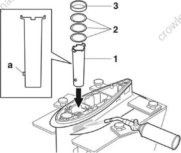
- While holding the special service tool “2”, strike the tool to check that the taper roller bearing outer race is installed properly.
TIP:
If a high-pitched metallic sound is produced when the special service tool is struck, the outer race is installed properly.
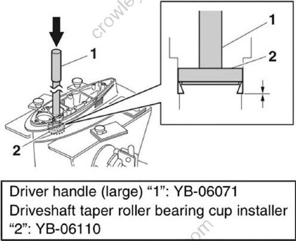
Driver handle (large)"1": YB-06071
Drive shaft taper roller bearing cup installer "2": YB-06110
- Install the water inlet covers “1” and “2”, nut “3”, and water inlet cover screw “4”, and then tighten the water inlet cover screw “4” to the specified torque.
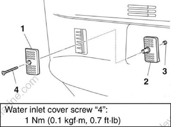
Water inlet cover screw "4": 1 Nm (0.1 kgf•m, 0.7 ft•lb)
Installing the shift rod
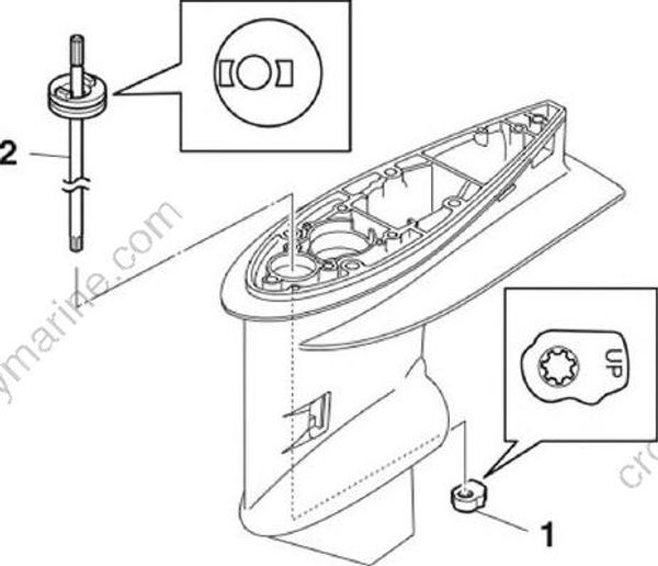
- Install the shift cam “1” and shift rod “2”.
Installing the drive shaft
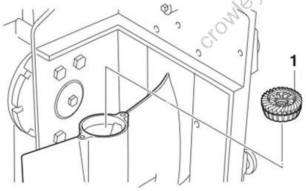
- Install the forward gear assembly “1"
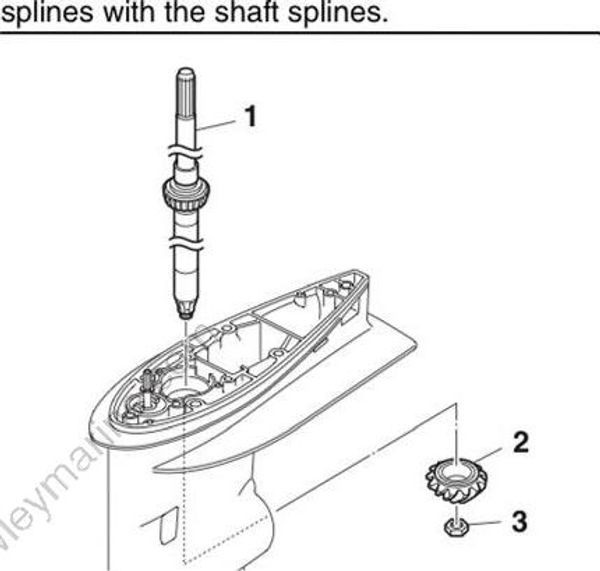
- Install the drive shaft assembly “1”, pinion “2”, and pinion nut “3”.
TIP:
When installing the pinion “2”, lift up the drive shaft “1” slightly, and then align the pinion splines with the shaft splines.
- Tighten the pinion nut “1” to the specified torque.
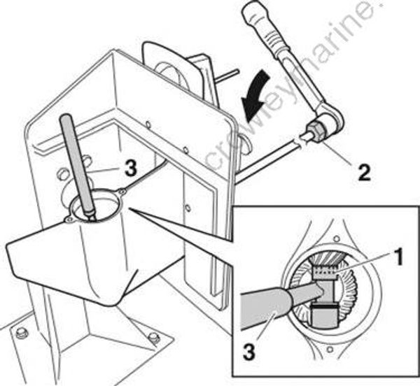
Drive shaft holder “2”: YB-06049
Pinion nut holder “3”: YB-06715
Pinion nut “1”: 74 Nm (7.4 kgf-m, 54.6 ft-lb)
Check that the drive shaft turns smoothly.
Install the washer “1”, oil seal housing “2”, and cover “3”.

Installing the propeller shaft housing assembly
- Install the washer “1” and propeller shaft “2” into the propeller shaft housing “3”.
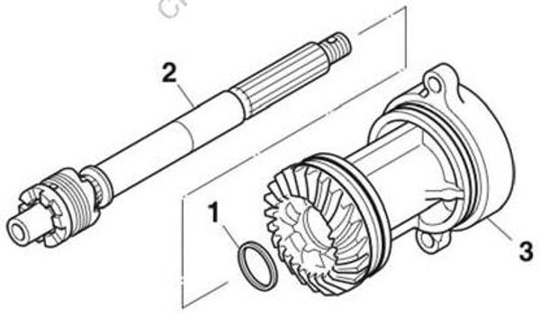
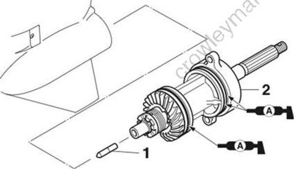
- Install the shift plunger “1” and propeller shaft housing assembly “2”.
- Tighten the propeller shaft housing bolts “1” to the specified torque.
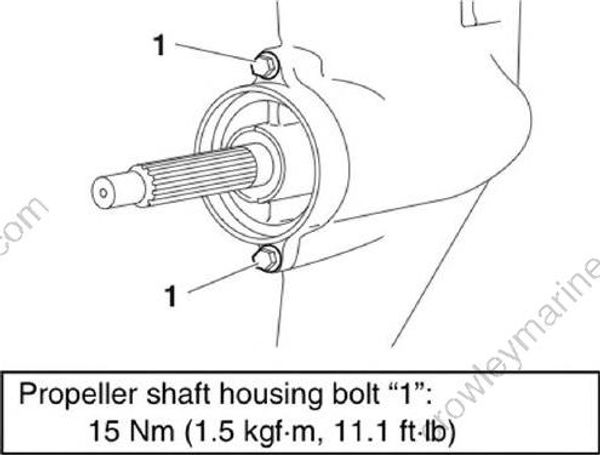
Propeller shaft housing bolt "1":
15 Nm (1.5 kgf•m, 11.1 ft•lb)
Installing the water pump
Install the plate “1” and rubber seal “2”
Install the dowels “3”, a new gasket “4”, and the outer plate cartridge “5”.

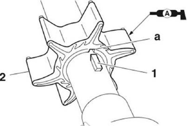
Install the impeller key "1"
Align the key way “a” in the impeller “2” with the impeller key “1”, and then install the impeller “2”.
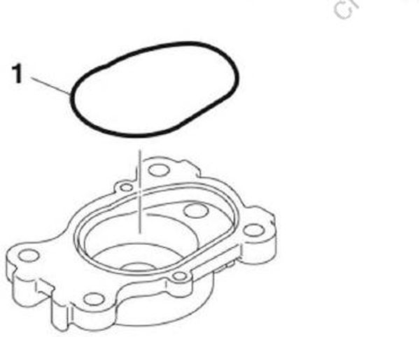
- Install a new O-ring “1”.
- Install the water pump housing assembly “1”.
NOTICE:
Do not turn the drive shaft counterclockwise. Otherwise, the water pump impeller may be damaged.
TIP:
While turning the drive shaft clockwise, push the water pump housing down to install it.

Checking the lower unit for air leakage
- Remove the gear oil check screw “1 ”, and then install the special service tool “2”.
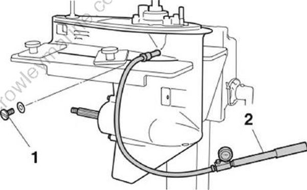
Leakage tester “2”: (commercially available)
- Apply the specified pressure to check that the pressure is maintained in the lower unit for 10 seconds or more.
NOTICE
Do not over pressurize the lower unit. Otherwise, the oil seals may be damaged.
Holding pressure: 68.6 kPa (0.69 kgf/cm2, 9.9 psi)
- If the specified pressure cannot be maintained, check the drive shaft, propeller shaft, and shift rod oil seals for
bends or damage.
Installing the lower unit (L-transom model)
WARNING
Do not hold the propeller with your hands when loosening or tightening it.
Make sure to disconnect the battery cables from the battery and the clip from the engine shut-off switch.
When installing the lower unit with the power unit installed, make sure to suspend the outboard motor. If the outboard motor is not suspended, it can fall suddenly and result in severe injuries.
- Check that the pin “a” is aligned with the mark “b” on the shift bracket “1”.
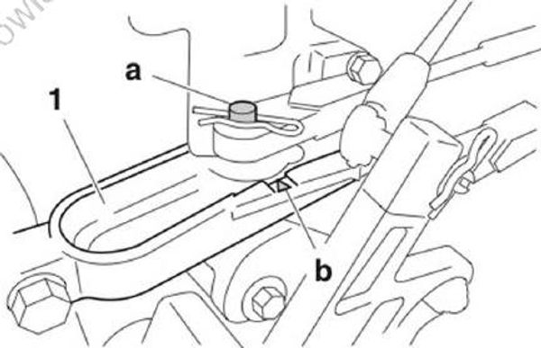
- Set the gear shift to the N position.
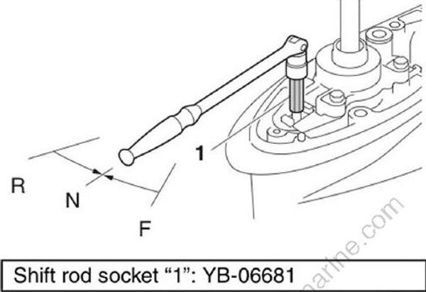
Shift rod socket "1": YB-06681
Install the dowels “1” and hose “2” into the lower unit.
Install the lower unit to the upper case, and then tighten the lower case mounting bolts “3” to the specified torque.
Install the trim tab “4” to its original position “a”.
Install the anode “5” and grommet “6”.

Lower case mounting bolt “3”: 40 Nm (4.0 kgf-m, 29.5 ft-lb)
- Install the spacer “1”, propeller “2”, washers “3” and “4”, and propeller nut “5”.
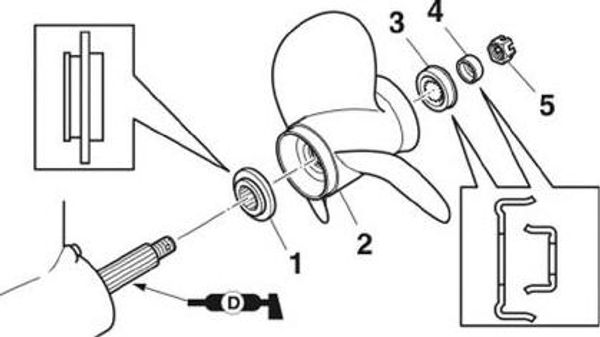
- Place a block of wood between the anti cavitation plate and the propeller to keep the propeller from turning, and then tighten the propeller nut “1” to the specified torque.
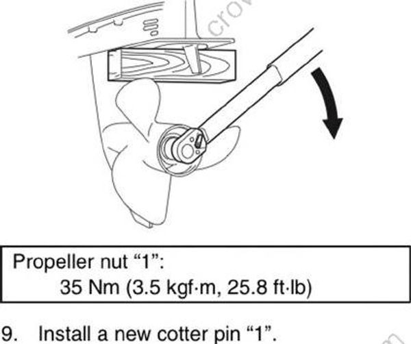
Propeller nut "1": 35 Nm (3.5 kgf•m, 25.8 ft•lb)
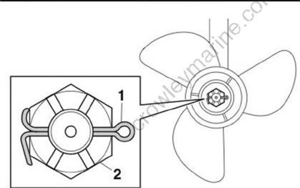
- Install a new cotter pin "1".
TIP:
If the slots in the propeller nut “2” are not aligned with the cotter pin hole, tighten the propeller nut until they are aligned.