

EXPLODED DIAGRAM
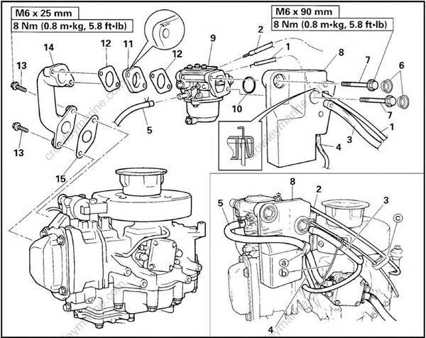
REMOVAL AND INSTALLATION CHART
| Step | Procedure/Part name | Q'ty | Service points |
|---|---|---|---|
| INTAKE SYSTEM REMOVAL | Follow the left "Step" for removal | ||
| 1 | Choke wire | NOTE: | |
| 2 | Throttle cable | * Disconnect the wire and cable from carburetor * Clamp the wire and cable with the cable clamp (c), after connected |
|
| 3 | Breather hose 1 | 09 mm NOTE: Clamp the fuel hose and breather hose with the hose clamp (b), after connected |
|
| 4 | Breather hose 2 | 07 mm |
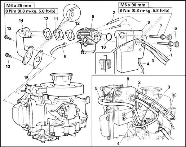
| Step | Procedure/Part name | Q'ty | Service points |
|---|---|---|---|
| 5 | Fuel hose | 1 | NOTE: When connecting the fuel hose, pass the fuel hose through the clamp (a) on the intake silenxer. |
| 6 | Grommet | 2 | |
| 7 | Bolt with washer | 2 | |
| 8 | Intake silencer ass'y | 1 | |
| 9 | Carburetor ass'y | 1 | |
| 10 | O-ring | 1 | |
| 11 | Spacer | 1 | |
| 12 | Gasket | 2 | |
| 13 | Bolt with washer | 2 | |
| 14 | Intake manifold | 1 | |
| 15 | Gasket | 1 | |
| Reverse the removal steps for installation. |
