

Charging system
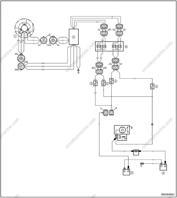
(1) Stator coil
(2) Rectifier Regulator
(3) Fuse(30 A)
(4) Starting battery
(5) Accessory battery
(6) Fuel pump driver and isolator
B : Black
G : Green
R : Red
W : White
Y : Yellow
G/W : Green/white
R/Y : Red/yellow
Checking the stator coil
Remove the intake silencer and disconnect the stator coil coupler.
Connect the test harness (3 pins) to the stator coil.
Install the intake silencer.
Do not start the engine when the intake silencer is not installed.
- Measure the stator coil output peak volt age. Replace the stator coil if below specification.
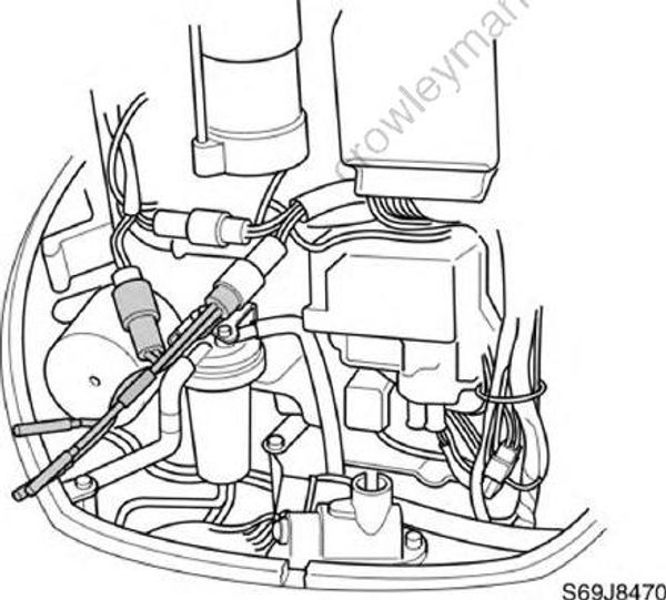
Digital multimeter: YU-34899-A
Peak voltage adaptor: YU-39991
Test harness (3 pins): YB-06770
Stator coil output peak voltage: Green (G) - Green (G)
| r/min | Unloaded | Unloaded | Unloaded |
|---|---|---|---|
| r/min | Cranking | 1,500 | 3,500 |
| DC V | 10 | 42 | 93 |
Green/white (G/W) - Green/white (G/W)
| r/min | Unloaded | Unloaded | Unloaded |
|---|---|---|---|
| r/min | Cranking | 1,500 | 3,500 |
| DC V | 9.0 | 34 | 78 |
Stator coil resistance (use as reference): Green (G) - Green (G)
0.28-0.42 Ω at 20 °C (68 °F)
0.24-0.36 Ω at 20 °C (68 °F)
Green/white (G/W) - Green/white (G/W)
0.24-0.36 Ω at 20 °C (68 °F)
0.20-0.31 Ω at 20 °C (68 °F)
Checking the Rectifier Regulator
- Remove the intake silencer and disconnect the Rectifier Regulator coupler.
- Connect the test harness (2 pins) to the Rectifier Regulator.
- Install the intake silencer.
Do not start the engine when the intake silencer is not installed.
- Measure the Rectifier Regulator output peak voltage. If below specification, measure the stator coil output peak voltage. Replace the Rectifier Regulator if the out put peak voltage of the stator coil is above specification.
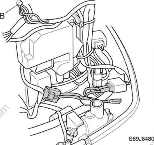
Disconnect the output lead couplers (blue) of the Rectifier Regulator when measuring the output peak voltage.
Digital multimeter: YU-34899-A
Peak voltage adaptor: YU-39991
Test harness (2 pins): YB-06787
Rectifier Regulator output peak voltage:
Red (R) - Black (B)
Red/yellow (R/Y) - Black (B)
| r/min | Unloaded | Unloaded |
|---|---|---|
| r/min | 1,500 | 3,500 |
| DC V | 13 | 13 |
