

Y-COP (optional)
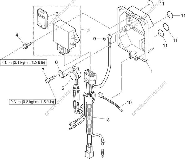
| No. | Part name | Q’ty | Remarks |
|---|---|---|---|
| 1 | Cover | 1 | |
| 2 | Control unit assembly | 1 | |
| 3 | Remote control transmitter | 2 | |
| 4 | Screw | 2 | M6 x 15 mm |
| 5 | Buzzer | 1 | |
| 6 | Bracket | 1 | |
| 7 | Screw | 1 | M6 x 19 mm |
| 8 | Main wire harness | 1 | |
| 9 | O-ring | 1 | |
| 10 | Plastic tie | 1 | |
| 11 | Seal | 4 |
Checking Y-COP
- Disconnect the Y-COP coupler “a”, and then measure the Y-COP input voltage.
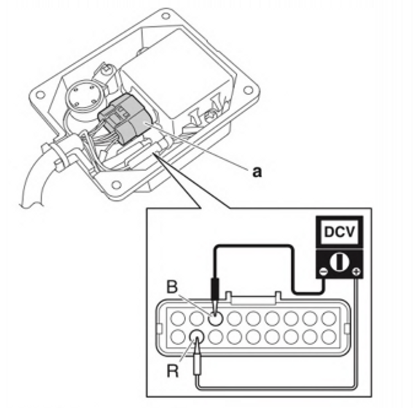
Y-COP input voltage : Red (R) - Black (B) 12 V (battery voltage)
- Connect the Y-COP coupler.
Checking the buzzer
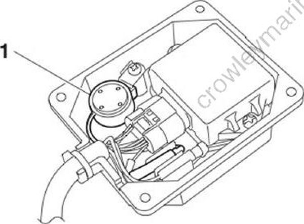
- Remove the Y-COP buzzer “1 ”.
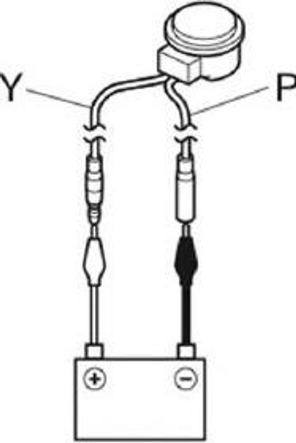
- Connect the battery leads to the Y-COP buzzer connectors, and then check that the Y-COP buzzer comes on. Replace the Y-COP buzzer if it does not come on.
- Measure the Y-COP buzzer input voltage.
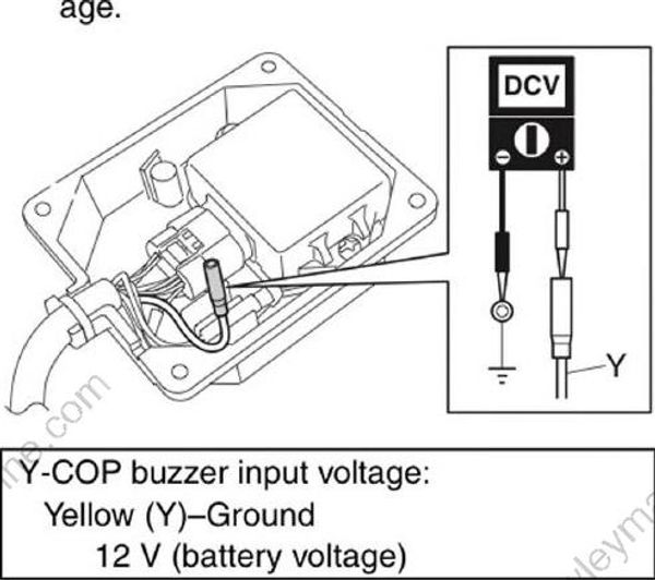
Y-COP buzzer input voltage : Yellow (Y) - Ground 12 V (battery voltage)
Checking the Y-COP main wire harness
- Remove the Y-COP main wire harness “1”.

- Check the wire harness for continuity.
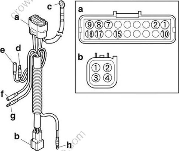
| Wire harness continuity: |
|---|
| a. Terminal 1-b. Terminal 3 |
| a. Terminal 2-d. Pink (P) |
| a. Terminal 7-b. Terminal 2 |
| a. Terminal 8-f. White (W) |
| a. Terminal 9-g. White (W) |
| a. Terminal 10-b. Terminal 4 |
| a. Terminal 15-b. Terminal 1 |
| a. Terminal 17-h. Red (R) |
| a. Terminal 17-e. Yellow (Y) |
| a. Terminal 18-c. White (W) |
- Install the Y-COP main wire harness “1”, O-ring “2”, and control unit “3”, and then tighten the control unit screws “4” to the specified torque.
NOTICE
Do not connect the connectors “a” and “b”. Otherwise, Y-COP may not operate properly.

Control unit screw “4” : 4 N-m (0.4 kgf-m, 3.0 ft-lb)
Checking the button cell battery
Replace the button cell battery in the remote control transmitter once in the first year, and once every two years thereafter.
- Remove the remote control transmitter cover “1”.

- Push the Yamaha logo on the remote control transmitter cover “1” and remove the button cell battery “2”.
NOTICE
Do not touch the button cell battery directly. Otherwise, the button cell battery could get corroded.

- Measure the button cell battery voltage.
TIP:
When disposing of button cell batteries, make sure to follow local disposal regulations.
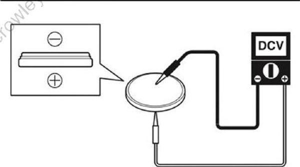
Button cell battery voltage - CR2016 (reference data) : 3 V
- Install the button cell battery “1” so that the positive side is facing the remote control transmitter cover “2”.
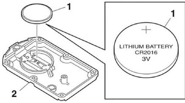
- Install the remote control transmitter cover “1”, and then tighten the remote control transmitter screws “2” to the specified torque in the order [1], [2], and so on.
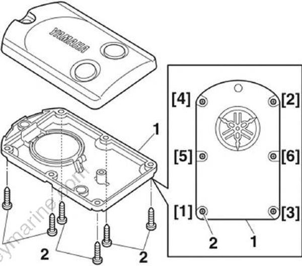
Remote control transmitter screw “2” : 0.1 N-m (0.01 kgf-m, 0.1 ft-lb)
