INSPECTION
All measuring instruments should be handled with special care, or the correct measurement is impossible.
On an instrument powered by dry batteries, they should be checked for voltage periodically and replaced, if necessary.
Low resistance measurement
When measuring the resistance of 10Ω or less using the digital tester, the correct measurement cannot be obtained because of the tester's internal resistance.
To obtain the correct value, subtract this internal resistance from the displayed measurement.
Correct value = Displayed measurement - Internal resistance
The internal resistance of the tester can be obtained by connecting both of its terminals.
IGNITION SYSTEM
Spark plug
Refer to page 3-11.
Spark plug cap
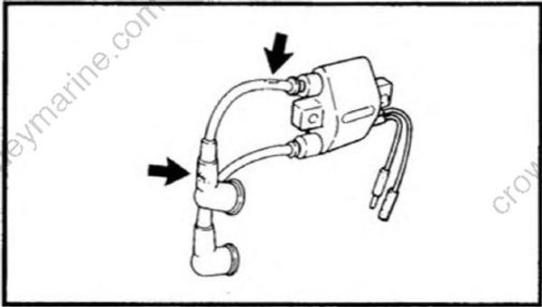
- Inspect:
• Spark plug cap
Loosen -> Tighten.
Crack/Damage -> Replace.
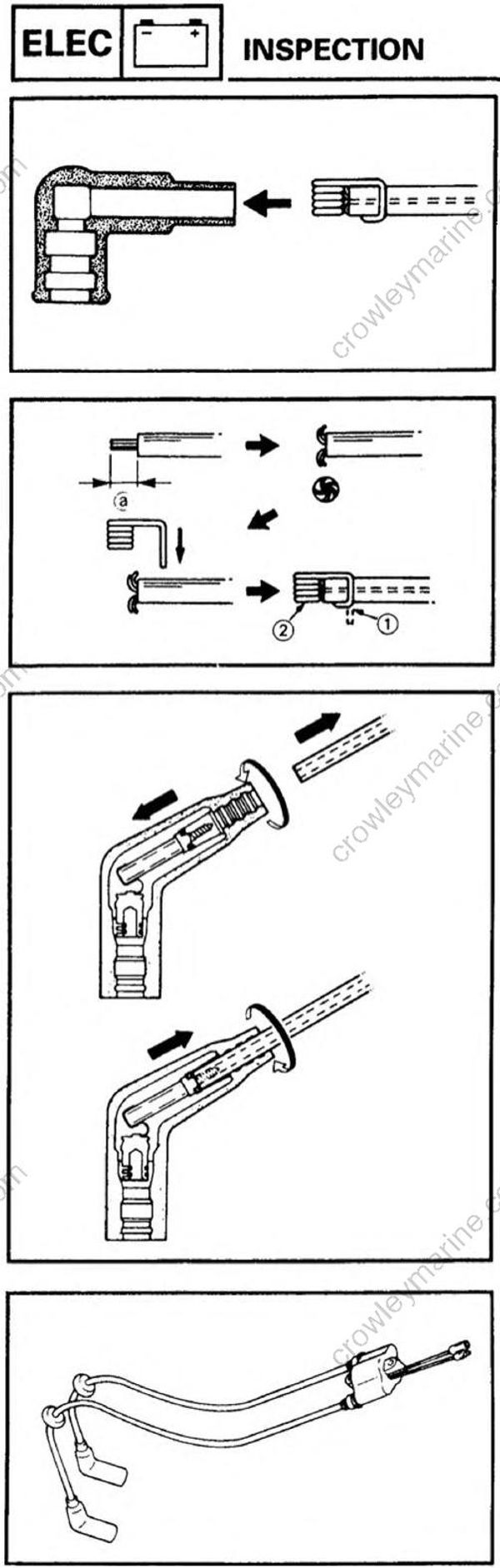
Replacement steps:(Except for Canada and Europe)
• Remove the spark-plug cap by pulling the cap, and remove the plug-cap spring from the high-tension cable.
• Cut about distance (a) off the end of the high-tension cable.
Distance (a):5 mm (0.2 in)
• Referring to the diagram, strip about 5 mm (0.2 in) of the insulation off the end of the high-tension cable, and fit the plug cap spring.
• Push the cap spring into the plug cap.
(1) Bend
(2) Contact
Replacement steps:
(For Canada and Europe)
• Remove the spark-plug cap by turning the cap counterclockwise.
Avoid removing the plug cap by pulling the wire hard. Remove it by turning in and out.
• Install the plug cap by turning the cap clockwise until it stops.
Ignition coil
Inspect:
• High tension cord
Crack/Damage -> Replace.Measure:
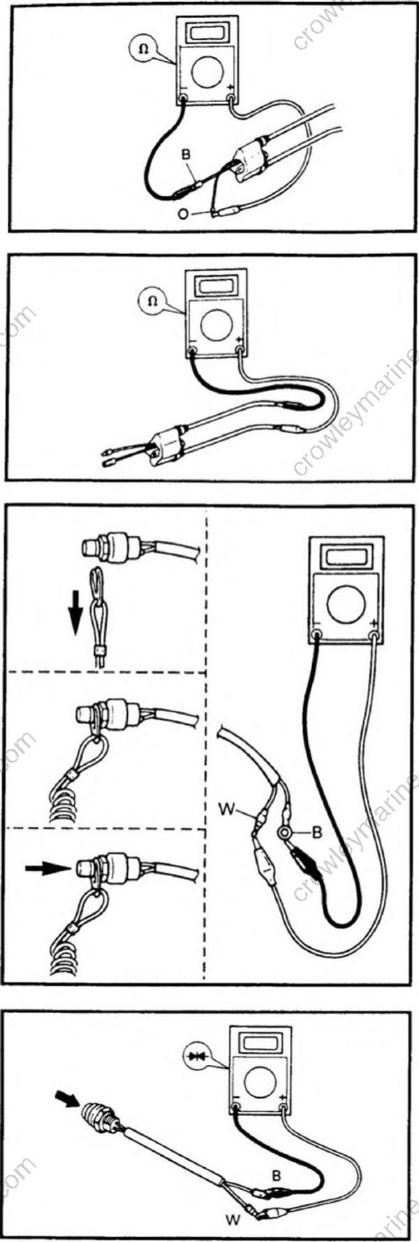
• Primary coil resistance
Out of specification-> Replace.
Primary coil resistance: Orange (O) - Black (B)
0.25 ~ 0.35Ω at 20’C (68' F)
When measuring the resistance of 10Ω or less using the digital tester, the correct measurement cannot be obtained. Refer to "Lower resistance measurement".
- Measure:
• Secondary coil resistance
Out of specification —> Replace.
Secondary coil resistance: High tension cord: 6.8 - 10.2 kΩ at 20'C (68'F)
Engine stop switch
- Check:
• Continuity
Out of specification -> Replace.
| Color: White - Black | |
|---|---|
| Remove the lock-plate | Continuity |
| Install the lock-plate | Discontinuity |
| Push the button | Continuity |
Stop switch
- Inspect:
• Continuity
Out of specification —> Replace.
| Color: White - Black | |
|---|---|
| Free | Discontinuity |
| Push the button | Continuity |
Ignition spark gap
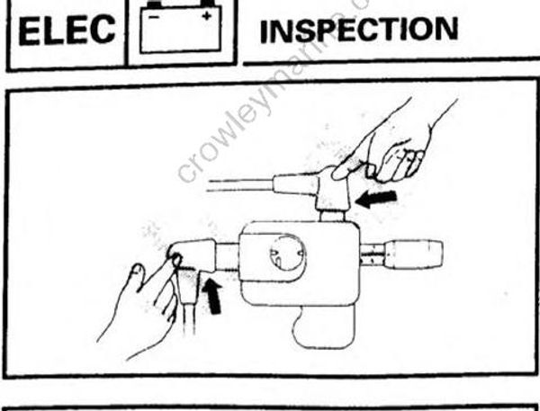
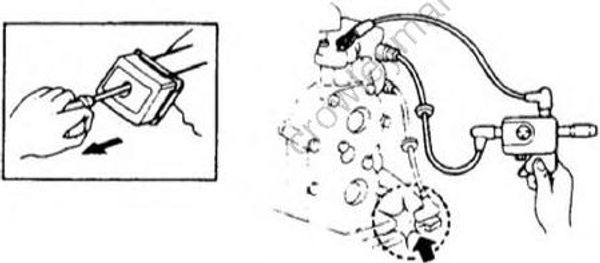
• While taking spark check be careful not to touch any connection of lead wires of the "Ignition spark gap tester".
• When doing the spark test, take special care not to allow leakage from the removed plug cap.
• This check is likely to produce sparks, so be sure that no flammable gas or fluid is in the vicinity.
- Check:
• Ignition spark gap
Out of specification ->Replace.
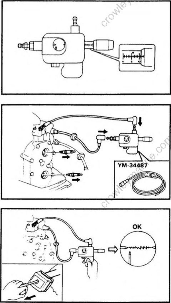
Checking steps:
• Adjust the spark gap to the specified by turning the adjust knob.
Spark gap tester: YM-34487/90890-06754
Spark gap: 9 mm (0.35 in)
• Connect the spark-plug cap to the spark gap tester.
• Remove the spark plugs from the engine.
• Cranking the engine and check sparks of ignition system seen through dis charge window.
Charge coil
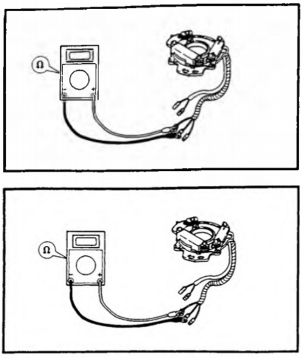
- Measure:
• Charge coil resistance
Out of specification -> Replace.
Charge coil resistance: Brown (Br) - Black (B) 81 ~ 99Ω at 20°C (68° F)
Pulser coil
- Measure:
• Pulser coil resistance
Out of specification-> Replace.
Pulser coil resistance: White/Red (W/R) - Black (B) 92 ~ 112Ω at 20 °C(68°F)
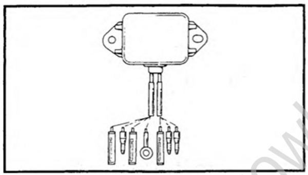
C.D.I. unit
- Measure:
• C.D.I. unit resistance
Out of specification -> Replace.
• Digital tester can not be used for this inspection. Use analogue tester.
• C.D.I. resistance values will vary from meter to meter, especially with electronic digital meters. For some testers, polarity of leads is reversed.
B : Black
Br: Brown
G : Green
O : Orange
W : White
W/R : White/Red
Unit: KΩ
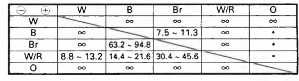
• : Needle swings once and returns to home position.
∞ : Discontinuity
C.D.I. system
• If there is no spark, or the spark is weak, continue with the C.D.I. test.
• If a good spark is obtained, the problem is not with the C.D.I. system, but possibly the spark plug or other component is defective.
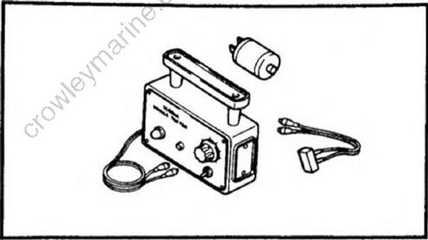
• Use the following special tool in this inspection.
C.D.I. tester: YU-91022-B
• If lamp dose not light, check tester batteries. If they are installed correctly and are good, check the clip leads for faulty connections. If no
fault can be found, refer to the warranty statement for instructions for sending the tester back to Electro-Specialities, inc.
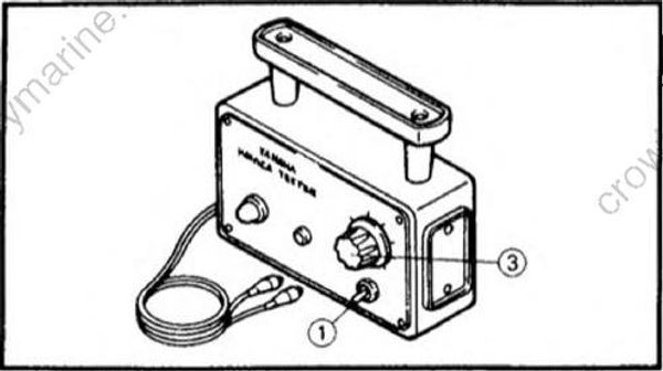
While taking C.D.I. unit check be careful not to touch any connection of lead wires of the "C.D.I. tester".
- Check:
• C.D.I. tester for high scale
No indication -> Replace the tester.
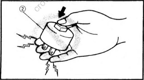
Checking steps:
• Place switch (1) in HIGH position.
• Plug the capacitive clip (2) into an electric outlet. (117 VAC for ten seconds)
Do not touch the plug pins on the capacitive clip while plugging it and depressing the button. An electric shock will result.
• Remove the capacitive clip from the outlet.
• Set the tester dial (3) to 50, or below.
• Connect the capacitive clip
Yellow (Y) lead -> Capacitive clip N terminal.
Red (R) lead -> Capacitive clip P terminal.
• Depress the button on the capacitive clip.
• The indicator lamp on the tester should light
- Check:
• C.D.I. tester for low scale
No indication —> Replace the tester.
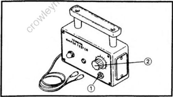
Checking steps:
• Place switch (1) in LOW position.
• Set the tester dial (2) to 50, or below.
• Connect the 12 V battery.
Red (R) lead -> Positive terminal. Yellow (Y) lead -> Negative terminal.
• The indicator lamp on the tester should light.
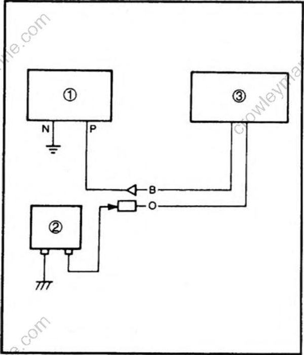
- Check:
• C.D.I. unit output (test #1) No indication Replace.
Checking steps:
• Disconnect the Black (B) and Orange (O) leads from the ignition coil.
• Remove the spark plugs.
• Connect the C.D.I. tester (1) and load coil (2) to C.D.I. unit (3) as shown.
C.D.I. tester: YU-91022-1
Load coil: YU-91022-3
In this test, connect the load coil, provided along with the tester, between the C.D.I.unit output and the ground.
• Set the tester switch and dial to specified.
| Range switch: | Dial setting: |
|---|---|
| H | 75 |
• Cranking the engine.
• The coil output varies greatly cranking speed.
• Cranking the cold engine with the plugs in and a weak battery cannot be found proper readings.
- Check:
• Charge coil output (test #2)
No indication ->Replace.
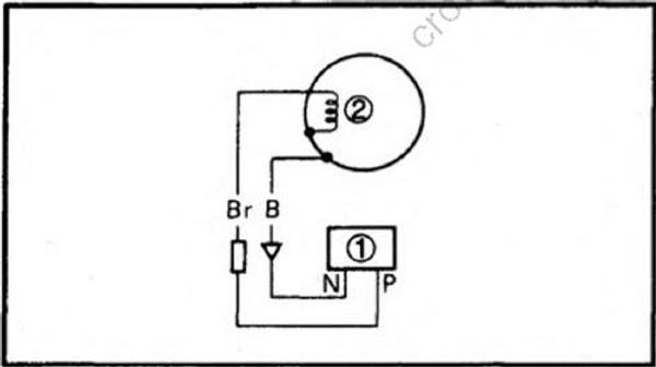
Checking steps:
• Disconnect the Brown (Br) and Black (B) leads from the charge coil.
• Remove the spark plugs.
• Connect the C.D.I. tester (1) to charge coil (2) as shown.
C.D.I. tester: YU-91022-1
• Set the tester switch and dial to specified.
| Range switch: | Dial setting: |
|---|---|
| H | 80 |
• Cranking the engine.
• The coil output varies greatly cranking speed.
• Cranking the cold engine with the plugs in and a weak battery can not be found proper readings.
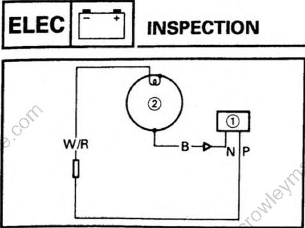
- Check:
• Pulser coil output (test #3)
No indication -> Replace.
Checking steps:
• Disconnect the White/Red (W/R) and Black (B) leads from the pulser coil.
• Remove the spark plugs.Connect the C.D.I. tester (1) to pulser coil (2) as shown.
C.D.I. tester: YU-91022-1
• Set the tester switch and dial to specified.
| Range switch: | Dial setting: |
|---|---|
| L | 80 |
• Cranking the engine.
• The coil output varies greatly cranking speed.
• Cranking the cold engine with the plugs in and a weak battery can not be found proper readings.
LIGHTING SYSTEM
Lighting coil
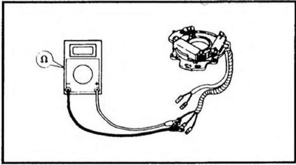
- Measure:
• Lighting coil resistance
Out of specification -> Replace.
Lighting coil resistance: Green (G) - Green (G) 0.36 ~ 0.44Ω 12 at 20 °C (68°F)
When measuring the resistance of 10 Q or less using the digital tester, the correct measurement cannot be obtained. Refer to "Lower resistance measurement".
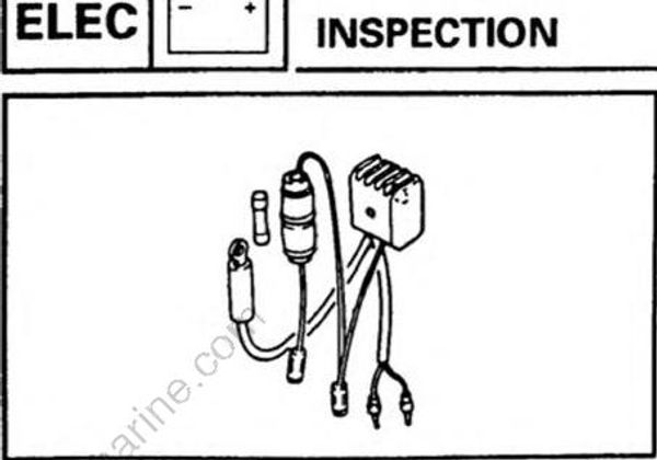
Rectifier regulator
(For Europe model)
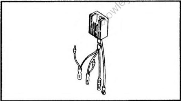
| 6CM | ✓ | 6CEM | |
|---|---|---|---|
| 8CM | ✓ | 8CEM |
- Check:
• Continuity
Out of specification -> Replace.
Digital tester can not be used for this inspection. Use the analogue tester.
B :Black
G :Green
G/W :Green/White
R :Red
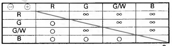
O : Continuity
∞ : Discontinuity
Rectifier
| 6CM | 6CEM | ✓ | |
|---|---|---|---|
| 8CM | 8CEM | ✓ |
- Check:
• Continuity
Out of specification -> Replace.
Digital tester can not be used for this inspection. Use the analogue tester.
B :Black
G1,2 :Green
R :Red
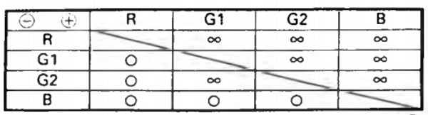
O : Continuity
∞ : Discontinuity
ELECTRIC STARTING SYSTEM
| 6CM | 6CEM | ✓ | |
|---|---|---|---|
| 8CM | 8CEM | ✓ |
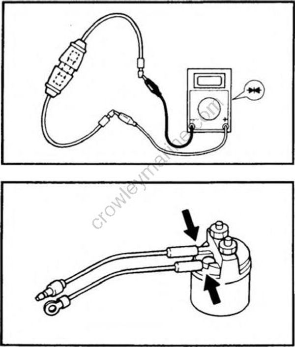
Fuse
- Check
• Fuse
Blown-> Replace
Fuse rating: 10A
Starter relay
- Inspect:
• Brown lead terminal
• Black lead terminal Loose ->Tighten.
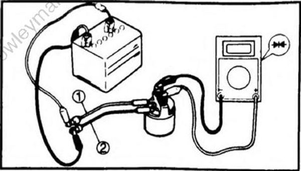
- Check:
• Relay operation
Does not function -> Replace.
Checking steps:
• Connect a tester (Ω x 1) between the terminals of the starter relay as shown.
• Connect a 12 V battery.
(1) Brown lead -> Positive terminal
(2) Black lead -> Negative terminal
• Check that there is continuity between the starter relay terminals.
Starter switch
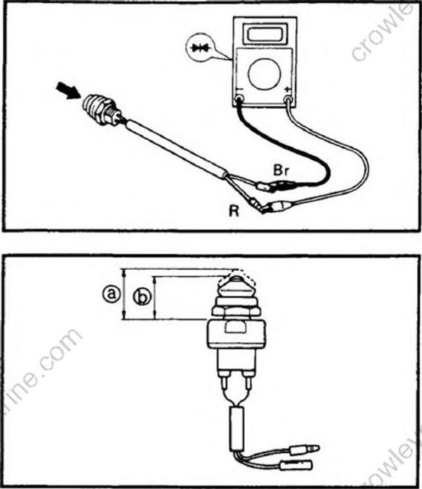
- Inspect:
• Continuity
Out of specification -> Replace.
| Distance | Color: Red - Brown |
|---|---|
| Free | Discontinuity |
| 18.5 ~ 19.5 mm (0.73 ~ 0.77 in) | Continuity |
Neutral switch
- Inspect:
• Continuity
Out of specification -> Replace.
| Distance | Color: Brown - Brown | |
|---|---|---|
| Free (a) | 19.6 ~ 20.5 mm (0.77 ~ 0.81 in) | Discontinuity |
| Push (b) | 18.5 ~ 19.5 mm (0.73 ~ 0.77 in) | Continuity |