

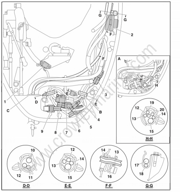
Port
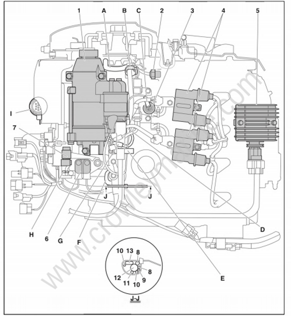
- Starter motor
- Thermo sensor
- Oil pressure switch
- Ignition coil
- Rectifier/Regulator
- Starter relay
- Starter fuse
- Lighting coil lead
- Starter relay lead
- Starter motor lead
- PTT relay lead
- Wire harness
- Negative battery cable
A. Route the lighting coil lead under the base of the flywheel magneto.
B. Install the thermo sensor lead, and then install the lighting coil lead and fasten them with the clamp.
C. Install the oil pressure switch lead in the direction shown in the illustration.
D. Route the oil pressure switch lead on the back side of the thermo sensor lead.
E. Install the clamp so that its open side is facing the starter motor.
F. Fit the grommet into the bolt so that the smaller diameter side is facing toward the engine.
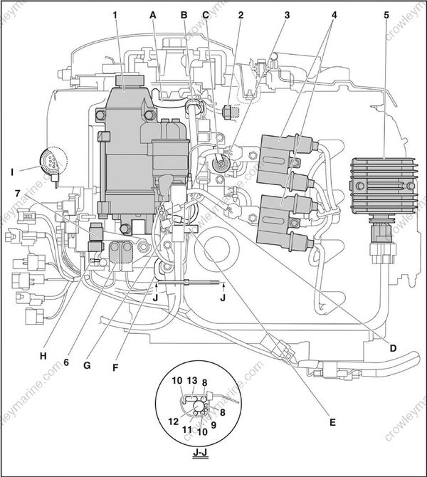
G. While holding the thicker ground terminal against the stopper.
H. Fasten the harnesses using the plastic tie so that its end is facing outward, and then cut its protruding end to less than 3 mm.
I. Pass the plastic ties from the top hole to the bottom hole and secure the main wire harness coupler using the plastic ties.
Starboard
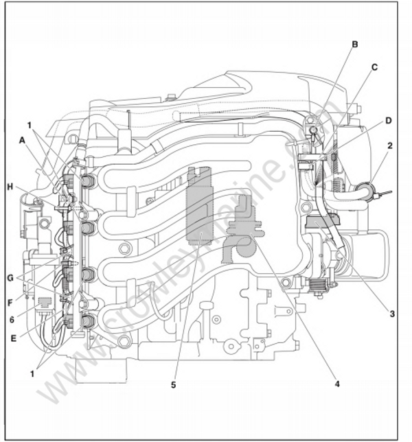
- Fuel injector
- Main wire harness coupler
- TPS
- ISC valve
- High-pressure fuel pump
- Water detection switch
A. Route the wire harness in front of the water detection switch coupler, and then fasten the wire harness to the water detection switch coupler using the plastic tie. Point the end of the plastic tie toward the inside of the fuel rail.
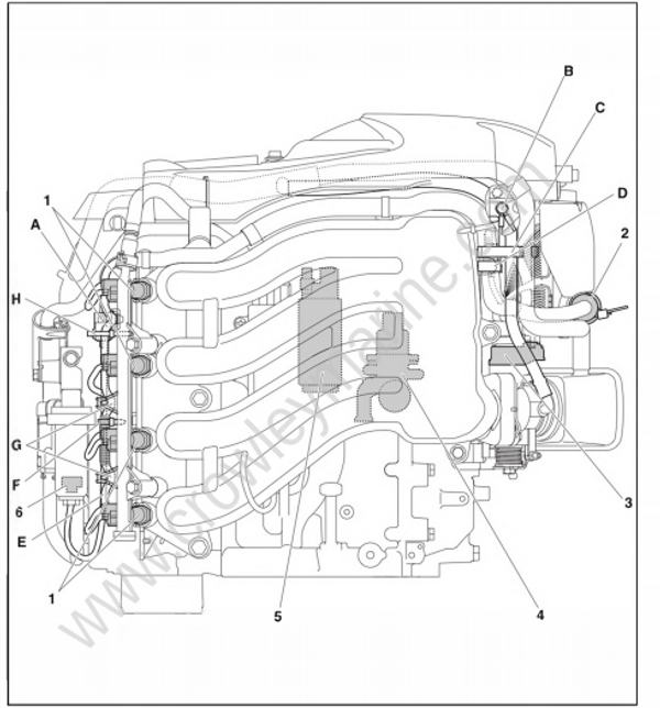
B. While holding the ground terminal against the stopper, tighten the bolt.
C. Hold the wire harness, vapor gas hose, and blowby hose.
D. Insert the protrusion on the wire harness into the intake manifold.
E. Route the water detection switch lead through the inside of the wire harness.
F. Pass the wire harness through the clamps.
G. Point the end of the plastic tie toward the inside of the fuel rail.
H. Insert the protrusion on the water detection switch coupler into the cylinder head cover.
Front
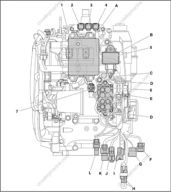
- Engine ECM
- Fuse (20 A) (battery)
- Fuse (20 A) (engine start switch, PTT switch)
- Fuse (20 A) (main relay)
- Main relay
- PTT relay
- YDIS coupler
A. Insert the protrusion on the wire harness into the bracket.
B. Install the grommet on the back side of the main relay.
C. Fasten the wire harness to the bracket using the plastic tie.
D. Insert the protrusion on the plastic tie into the bracket.
E. Fasten the Rectifier/Regulator lead to the starter using the plastic tie. Point the end of the plastic tie towards the engine.
F. To PTT switch
G. To shift position switch
H. To tilt limiter
I. To trim sensor
J. To conventional gauge
K. To trolling switch
L. To multi-hub
Top
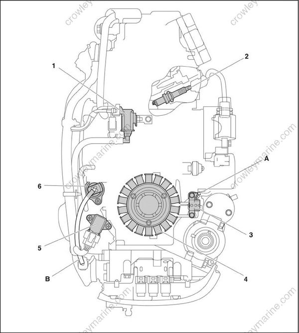
- Vapor shut-off valve
- Spark plug
- Pulser coil
- Lighting coil (stator assembly)
- Intake air pressure/temperature sensor
- ISC valve
A. Fasten the pulser coil lead to the boss portion of the flywheel magneto base.
B. Route the ISC valve lead to the inside of the air pressure/temperature lead.
Bottom cowling
- Shift position switch
- PTT switch
- Trim sensor coupler
- Trolling switch coupler
- Shift position switch coupler
- Trim sensor connector
- Conventional gauge coupler
- PTT switch coupler
- CL Gauge communication coupler
- Conventional gauge harness
- Shift position switch lead
- PTT switch lead
- PTT motor lead
- Trim sensor lead
- Wire harness
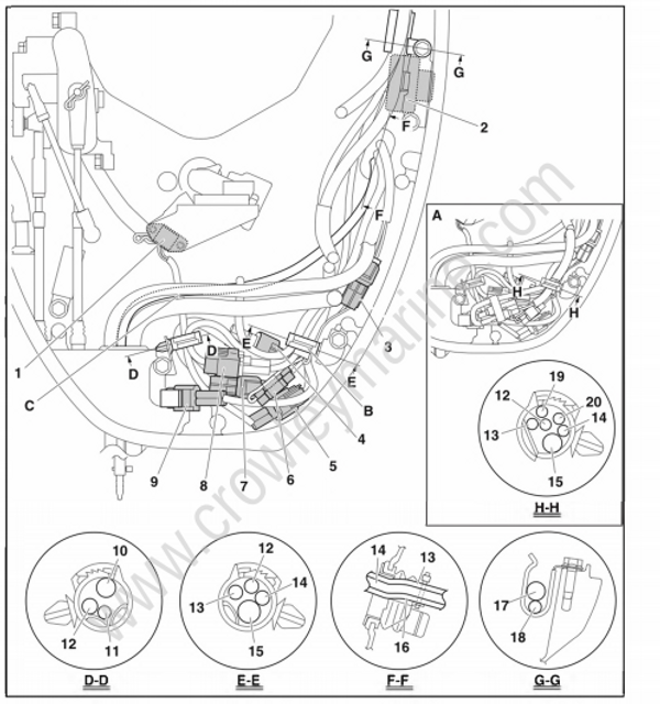
- Speedometer hose
- Water pressure sensor harness
- Water detection switch lead
- Tilt limiter switch lead
- Tilt limiter harness
A. Tilt limiter model
B. Clamp the wire harness at the tape.
C. Route the speedometer hose under the shift position switch lead.
Tiller handle
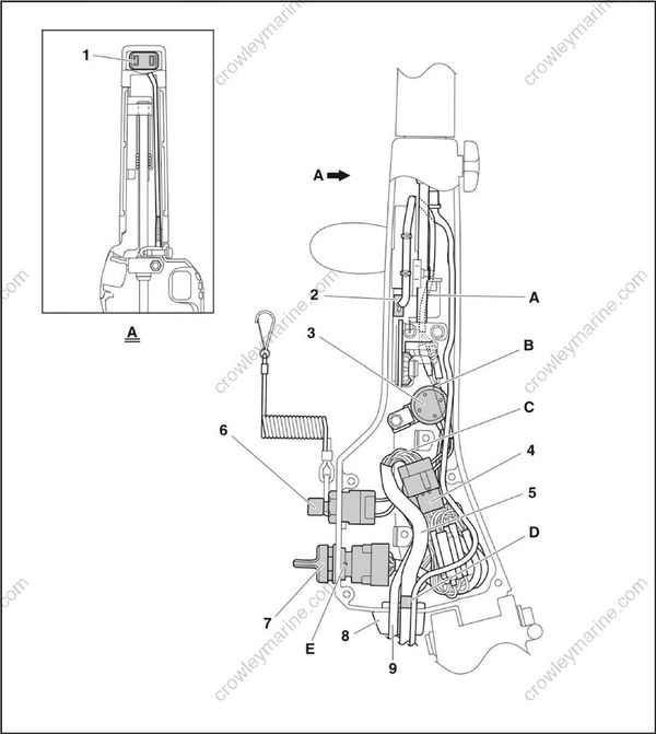
- PTT switch
- Neutral switch
- Alert buzzer
- Engine start switch coupler
- Extension wire harness
- Engine shut-off switch
- Engine start switch
- Grommet
- Alert indicator harness (optional)
A. Route the neutral switch leads (blue and black) under the control link assembly.
B. Route the neutral switch leads (brown) under the buzzer.
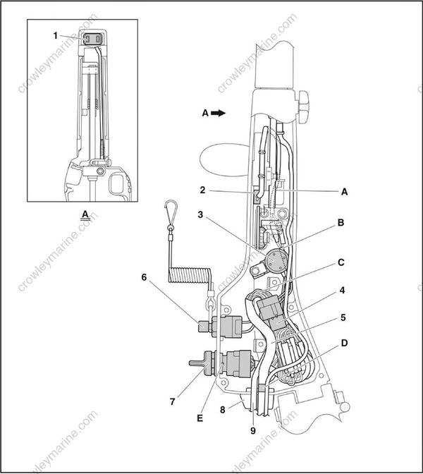
C. Bend the extension wire harness “5”, and then connect the harness coupler. The harness bending position must be 10.0 mm (0.39 in) or more away from the engine start switch coupler “4”. The bend radius should be 10.0 mm (0.39 in) or more.
D. Align the tape end of the extension wire harness “5” with the end of the grommet “8”.
E. Install the engine start switch “7” so that the hole in the switch is facing up.
