Checking the electrical component Using the YDIS
When checking the TPS, ISC valve, high pressure fuel pump, fuel injector, and related sensors, use the YDIS.
TIP:
When deleting the diagnosis record in the YDIS, make sure to check the time that the trouble codes were detected.
When checking the input voltage of a part, the coupler or connector must be disconnected. As a result, the engine ECM determines that the part is disconnected and a trouble code is detected. Therefore, make sure to delete the diagnosis record after checking the input voltage.
To connect and operate the YDIS, see the YDIS (Ver. 2.10 or later) instruction manual.
Measuring the peak voltage
WARNING
When measuring the peak voltage, do not touch any of the connections of the digital tester probes.
NOTICE
When measuring the peak voltage between the terminals of an electrical
component using the digital tester, make sure that the leads do not contact any
metal parts. Otherwise, the electrical component may short-circuit and be damaged.
To check the electrical components or measure the peak voltage, use the special service tools. A malfunctioning electrical component can be checked easily by measuring the peak voltage. The specified engine speed when measuring the peak voltage is affected by many factors such as fouled spark plugs or a weak battery. If one of these factors is present, the peak voltage cannot be measured properly.
TIP:
Before measuring the peak voltage, check all of the wire harnesses for corrosion. Also, make sure that the wire harnesses are connected properly and that the battery is fully charged.
Use peak voltage adapter with the recommended digital circuit tester.
Connect the positive pin of peak voltage adapter to the positive terminal of the digital tester, and connect the negative pin to the negative terminal.
When measuring the peak voltage, set the digital circuit tester to the DC voltage mode.

Digital multimeter : YU-34899-A
Peak volt adapter : YU-39991
Using the digital tester
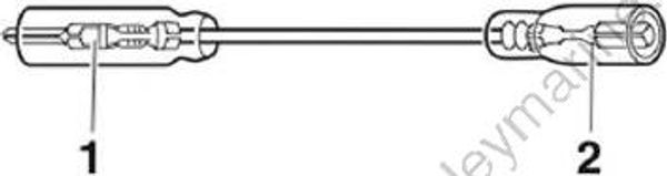
The electrical technical data applies to the measurements taken using the Yamaha recommended tester.The resistance values shown are the values taken before the engine is started. The actual resistance may vary depending on the environmental conditions and ambient temperature. The input voltage changes depending on the battery voltage. If the tester probe cannot be inserted into the coupler, prepare a test lead suitable for the measurement.
Digital multimeter : YU-34899-A
Test lead :
Terminal, male “1” : 9E212-10303
Terminal, female “2” : (commercially available)
Engine control unit and component
Checking the main relay
Remove the junction box cover and main relay “1”.
Disconnect the main relay coupler “a”.
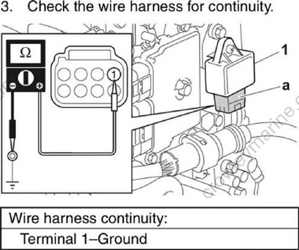
- Measure the input voltage between the terminal and ground.

Main relay input voltage : Terminal 5-Ground 12 V (battery voltage)
- Turn the engine start switch to ON, and then measure the input voltage between the terminal and ground.

Main relay input voltage : Terminal 2-Ground 12 V (battery voltage)
Turn the engine start switch to OFF.
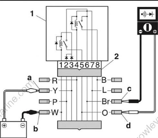
Connect the special service tool “2” to the main relay “1”.
Connect the positive battery lead to the connector “a”, connect the negative battery lead to the connector “b”, and then check for continuity between the connectors “c” and “d”. Replace the relay if out of specification.
NOTICE
Do not reverse the battery leads.