

EXPLODED DIAGRAM
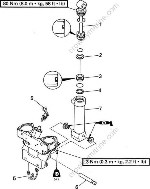
REMOVAL AND INSTALLATION CHART
| Step | Procedure/Part name | Q’ty | Service points |
|---|---|---|---|
| TILT CYLINDER DISASSEMBLY | Follow the left "Step" for removal | ||
| PTT unit | Refer to "POWER TRIM AND TILT UNIT REMOVAL" | ||
| 1 | Tilt piston assembly | 1 | |
| 2 | Backup ring | 1 | |
| 3 | Free piston | 1 | |
| 4 | Backup ring | 1 | |
| 5 | Delivery pipe | 2 | |
| 6 | Mount pin | 1 | |
| 7 | Tilt cylinder | 1 | |
| Reverse the removal steps for installation. |
SERVICE POINTS
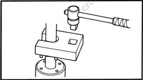
Tilt cylinder removal and installation
- Loosen and tighten:
- Tilt cylinder end screw
Tilt piston inspection
- Inspect:
- Tilt piston
Excessive scratch -> Replace.
Tilt rod inspection
- Inspect:
- Tilt rod
Bend/Excessive corrode -> Replace.
Rust lightly -> Polish (with #400-600 abrasive paper).
Tilt cylinder assembly
- Fill:
- PTT fluid
PTT fluid:
ATF (Dexiron type II)
Depress the tilt rod fully and fill the inner cylinder with ATF before installing the end screw.
