

Power trim and tilt unit
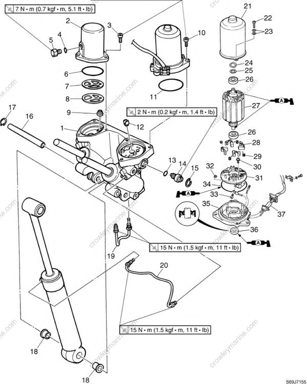
| No. | Part name | Q’ty | Remarks |
|---|---|---|---|
| 1 | Cylinder block | 1 | |
| 2 | Reservoir | 1 | |
| 3 | Bolt | 3 | M8 x 20 mm |
| 4 | O-ring | 1 | Not reusable |
| 1.9 x 12.6 mm | |||
| 5 | Reservoir cap | 1 | M12 x 10 mm |
| 6 | O-ring | 1 | Not reusable |
| 7 | Sheet | 1 | |
| 8 | Filter | 1 | |
| 9 | Spacer | 1 | |
| 10 | Bolt | 3 | M8 x 20 mm |
| 11 | O-ring | 1 | Not reusable |
| 2.4 x 22.6 mm | |||
| 12 | Joint | 1 | |
| 13 | O-ring | 1 | Not reusable |
| 14 | Manual valve | 1 | |
| 15 | Circlip | 1 | |
| 16 | Shaft | 1 | |
| 17 | Circlip | 1 | |
| 18 | Bushing | 2 | |
| 19 | Pipe | 1 | |
| 20 | Pipe | 1 | |
| 21 | Yoke | 1 | |
| 22 | Bolt | 2 | M5 x 12 mm |
| 23 | Washer | 4 | |
| 24 | Wave washer | 1 | |
| 25 | Washer | 1 | |
| 26 | Bearing | 2 | |
| 27 | Armature | 1 | |
| 28 | Brush | 4 | |
| 29 | Spring | 4 | |
| 30 | Screw | 2 | M4 x 12 mm |
| 31 | Brush holder | 1 | |
| 32 | Nut | 2 | |
| 33 | Screw | 2 | M4 x 6 mm |
| 34 | O-ring | 1 | Not reusable |
| 35 | PTT motor base | 1 | |
| 36 | Oil seal | 1 | Not reusable |
| 37 | PTT motor lead | 1 |
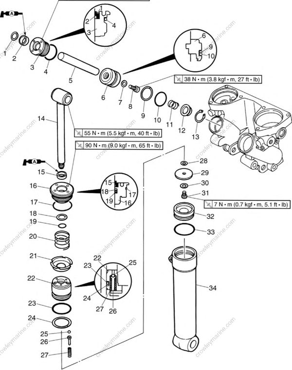
| No. | Part name | Q’ty | Remarks |
|---|---|---|---|
| 1 | Circlip | 2 | |
| 2 | Dust seal | 2 | Not reusable |
| 3 | Trim cylinder end screw | 2 | |
| 4 | O-ring | 2 | Not reusable |
| 5 | Trim ram | 2 | |
| 6 | Trim piston | 2 | |
| 7 | Washer | 2 | |
| 8 | Bolt | 2 | M8 x 20 mm |
| 9 | Backup ring | 2 | |
| 10 | O-ring | 2 | Not reusable |
| 11 | Spring | 2 | |
| 12 | Adapter | 2 | |
| 13 | Circlip | 2 | |
| 14 | Tilt ram | 1 | |
| 15 | Dust seal | 1 | Not reusable |
| 16 | Tilt cylinder end screw | 1 | |
| 17 | O-ring | 1 | Not reusable |
| 18 | Backup ring | 1 | |
| 19 | O-ring | 1 | Not reusable |
| 20 | Spring | 1 | |
| 21 | Adapter | 1 | |
| 22 | Tilt piston | 1 | |
| 23 | O-ring | 1 | Not reusable |
| 24 | Backup ring | 1 | |
| 25 | Ball | 5 | |
| 26 | Pin | 5 | |
| 27 | Spring | 5 | |
| 28 | Washer | 1 | |
| 29 | Plate | 1 | |
| 30 | Washer | 1 | |
| 31 | Bolt | 1 | M6 x 10 mm |
| 32 | Free piston | 1 | |
| 33 | O-ring | 1 | Not reusable |
| 34 | Tilt cylinder | 1 |
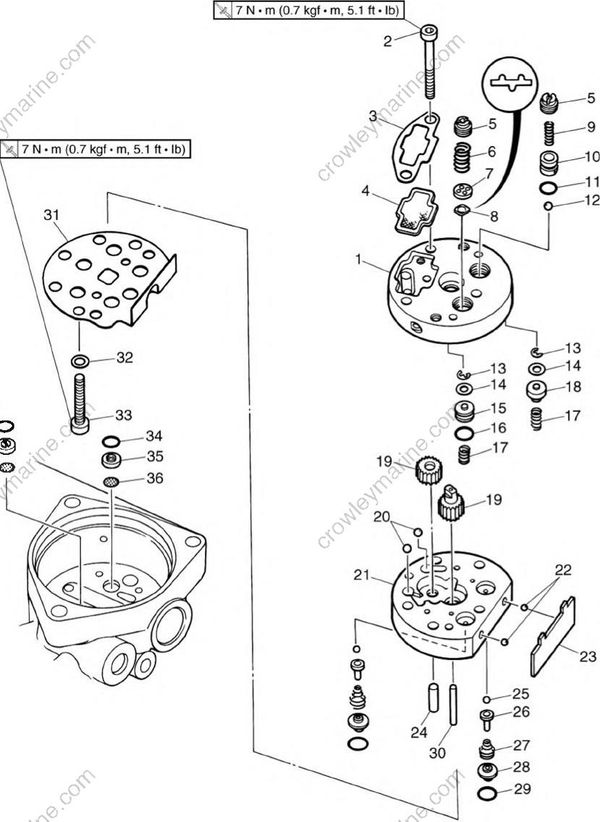
| No. | Part name | Q’ty | Remarks |
|---|---|---|---|
| 1 | Gear housing 1 | 1 | |
| 2 | Bolt | 3 | M5 x 40 mm |
| 3 | Plate | 1 | |
| 4 | Filter | 1 | |
| 5 | Valve lock screw | 2 | |
| 6 | Down-relief spring | 1 | |
| 7 | Valve support pin | 1 | |
| 8 | Relief valve seal | 1 | |
| 9 | Up-relief spring | 1 | |
| 10 | Valve support pin | 1 | |
| 11 | O-ring | 1 | Not reusable |
| 1.8 x 11.35 mm | |||
| 12 | Ball | 1 | |
| 13 | Circlip | 2 | |
| 14 | Main valve seal | 2 | |
| 15 | Shuttle piston | 1 | |
| 16 | O-ring | 1 | Not reusable |
| 17 | Return spring | 2 | |
| 18 | Shuttle piston | 1 | |
| 19 | Drive gear | 2 | |
| 20 | Ball | 2 | |
| 21 | Gear housing 2 | 1 | |
| 22 | Ball | 2 | |
| 23 | Manual release spring | 1 | |
| 24 | Dowel pin | 1 | |
| 25 | Ball | 2 | |
| 26 | Pin | 2 | |
| 27 | Spring | 2 | |
| 28 | Spacer | 2 | |
| 29 | O-ring | 2 | Not reusable |
| 1.9 x 9.6 mm | |||
| 30 | Dowel pin | 2 | |
| 31 | Bracket | 1 | |
| 32 | Washer | 2 | |
| 33 | Bolt | 2 | |
| 34 | O-ring | 2 | Not reusable |
| 1.9 x 9.6 mm | |||
| 35 | Spacer | 2 | |
| 36 | Filter | 2 |
Disassembling the power trim and tilt motor
- Remove the PTT motor screws (1), then the yoke (2).
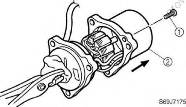
Do not allow grease or oil to contact the commutator.
Place a clean cloth over the end of the armature shaft and carefully pull the armature from the yoke with a pair of pliers as shown.
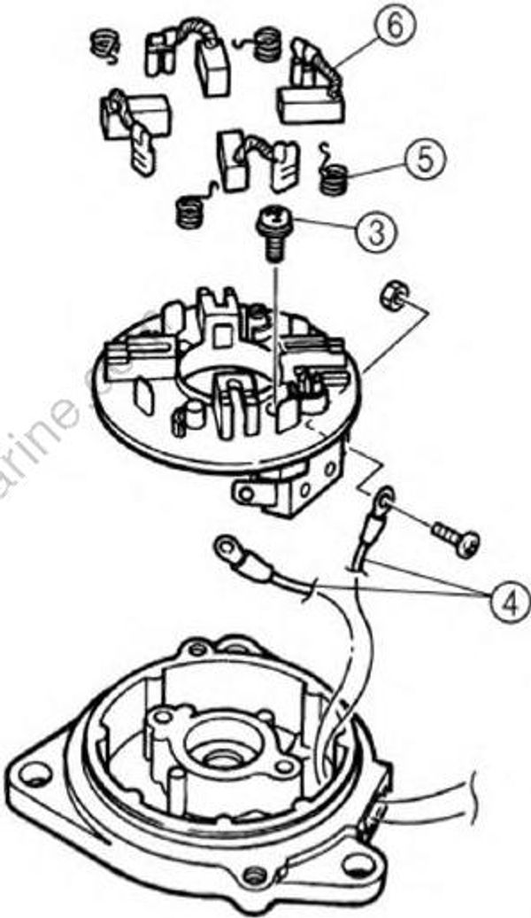
- Remove the screws (3) disconnect the PTT motor leads (4), and then remove the springs (5) and brushes (6).
Checking the power trim and tilt motor
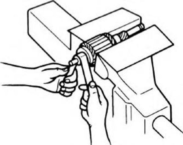
- Check the commutator for dirt or foreign substances. Clean with #600 grit sand paper if necessary.
Check the commutator undercut for dirt or foreign substances. Clean with com pressed air if necessary.
Measure the commutator diameter (a). Replace if out of specification.
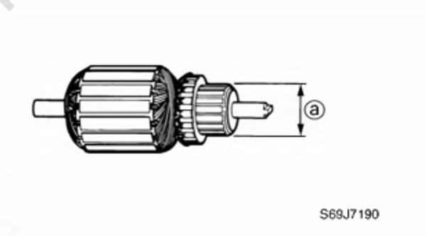
Commutator diameter limit (a): 25.0 mm (0.98 in)
- Check the armature coil for continuity. Replace if out of specifications.
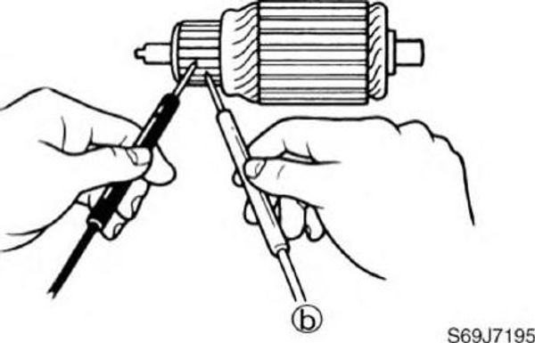
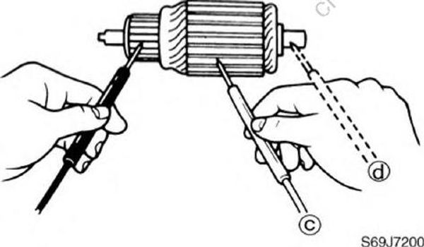
| Armature coil continuity | Armature coil continuity |
|---|---|
| Commutator segments (b) | Continuity |
| Segment-laminations (c) | No continuity |
| Segment-shaft (d) | No continuity |
- Check the circuit breaker for continuity. Replace the brush holder if there is no continuity.
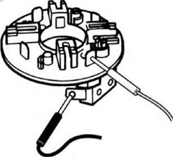
- Measure the brush length. Replace if out of specification.
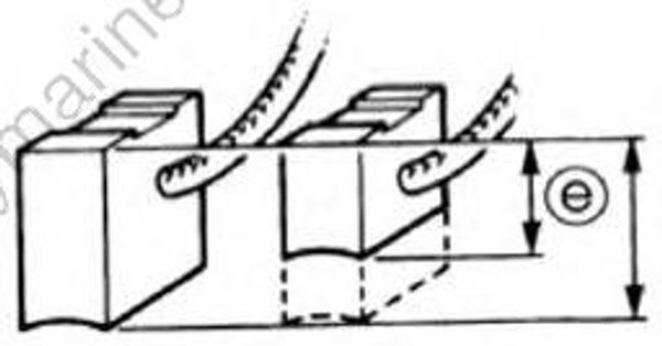
Brush length limit 4.0 mm (0.16 in)
Check the base for corrosion or damage. Replace if necessary.
Check the bearing for damage or wear. Replace if necessary.
Assembling the power trim and tilt motor
- Install the new oil seal (1) and bearing (2) into the motor base (3) as shown.
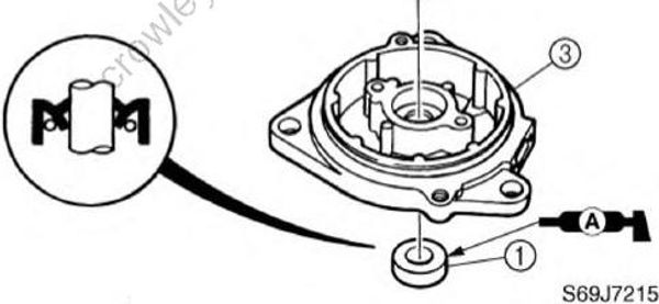
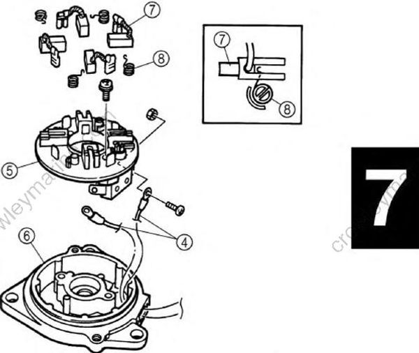
Connect the PTT motor leads (4) to the brush holder (5) and then install the brush holder (5) to the motor base (6).
Install the brushes (7) and springs (8) to the brush holder as shown.
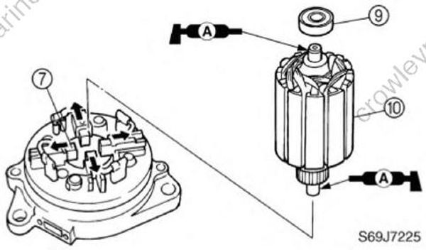
Install the bearing (9) to the armature (10).
Push the brushes (7) into the holders, and then install the armature (10).
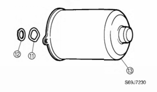
- Install the wave washer (11) and washer (12) into the yoke (13).
- Install the new O-ring and yoke (13) to the motor base.
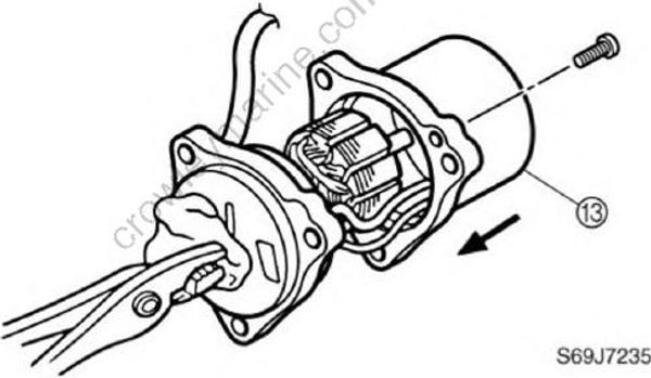
Place a clean cloth over the end of the armature shaft and carefully push the armature from the yoke with a pair of pliers as shown.
Checking the hydraulic pressure
Check the hydraulic pressure. Check the internal parts if out of specification.
Fully extend the power trim and tilt rams.
Loosen the pipe joints (1), and then remove the pipe joint (a).
Install the PTT oil pressure gauge adapter set (4).
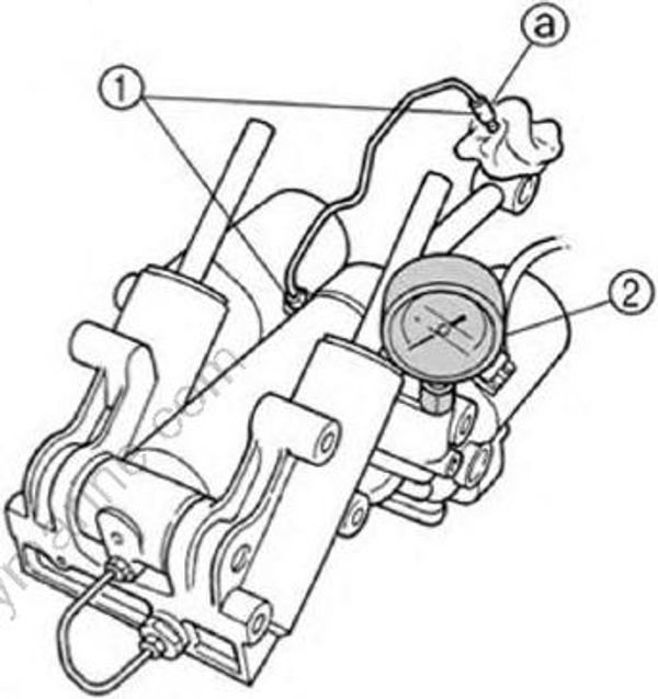
Cover the removed pipe joint (a) with a rag.
PTT oil pressure gauge adapter set: YB-06580
- Connect the PTT motor leads to the battery terminals to retract the tilt ram, and then measure the hydraulic pressure.
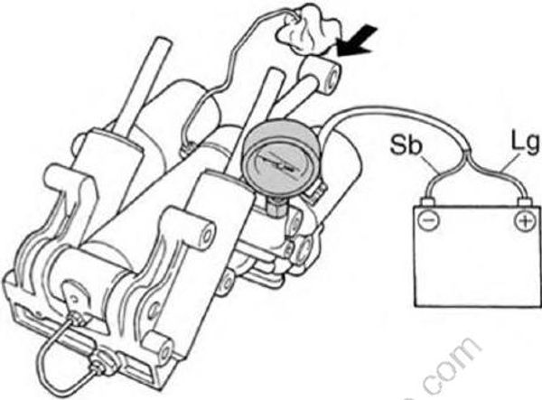
| Ram | PTT motor lead | Battery terminal |
|---|---|---|
| Down | Light green (Lg) | (+) |
| Down | Sky blue (Sb) | (-) |
Hydraulic pressure (down): 6.7-8.7 MPa (68-89 kgf/cm2)
- Reverse the PTT motor leads between the battery terminals to fully extend the trim and tilt rams.
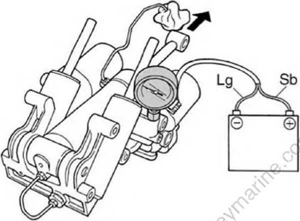
| Ram | PTT motor lead | Battery terminal |
|---|---|---|
| Up | Sky blue (Sb) | (+) |
| Up | Light green (Lg) | (-) |
Remove the PTT oil pressure gauge adapter set (2).
Install the pipe joints (1), and then tightening them to the specified torque.
Pipe joint (1): 15 N⋅m (1.5 kgf⋅m, 11 ft⋅lb)
Connect the PTT motor leads to the battery terminals to fully retract the trim and tilt rams.
Loosen the pipe joints (3) and then remove the pipe joint (b).
Install the PTT oil pressure gauge adapter set (2).
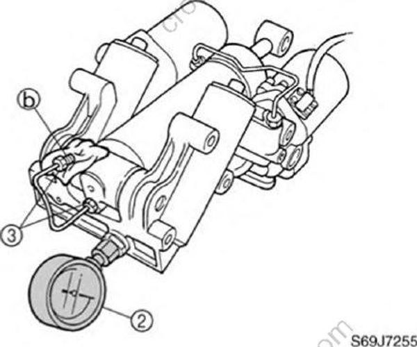
Cover the removed pipe joint (b) with a rag.
PTT oil pressure gauge adapter set: YB-06580
- Connect the PTT motor leads to the battery terminals to extend the tilt ram, and then measure the hydraulic pressure.
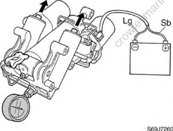
Hydraulic pressure (up): 12.2-14.2 MPa (124-145 kgf/cm2)
- Reverse the PTT motor leads between the battery terminals to fully retract the trim and tilt rams.
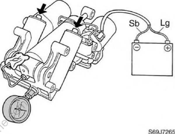
Remove the PTT oil pressure gauge adapter set (2).
Install the pipe joints (3), and then tightening them to the specified torque.
Pipe joint (3): 15 N⋅m (1.5 kgf⋅m, 11 ft⋅lb)
- After measuring the hydraulic pressure, connect the PTT motor leads to the battery terminals to fully extend the trim and tilt rams.
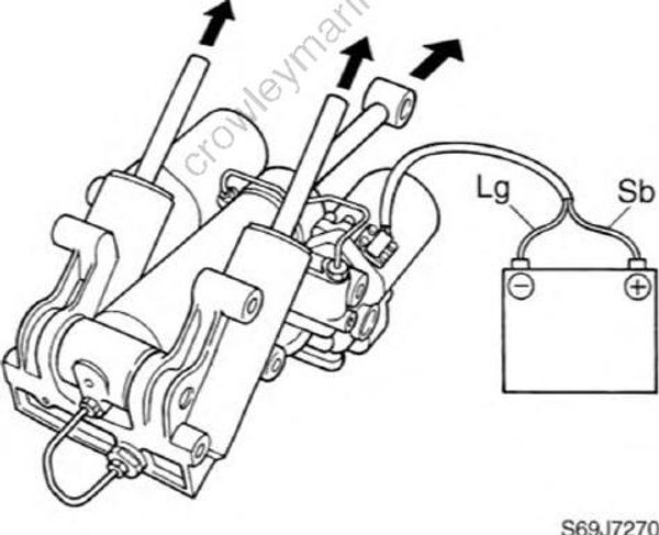
Remove the reservoir cap, and then check the fluid level in the reservoir.
If necessary, add fluid of the recommended type to the correct level.
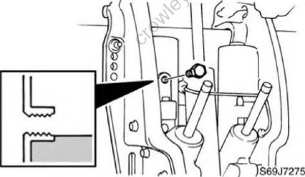
If the fluid is at the correct level, the fluid should overflow out of the filler hole when the cap is removed.
Recommended power trim and tilt fluid: ATF Dexron II
- Install the reservoir cap.
Disassembling the gear pump
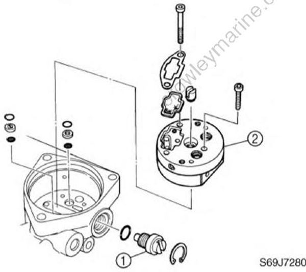
- Remove the manual valve (1) and gear pump (2).
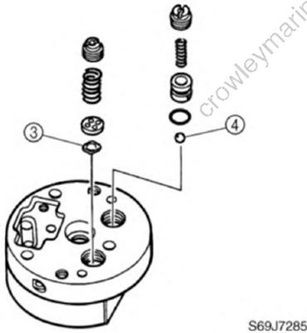
- Remove the relief valve seal (3) and ball (4).
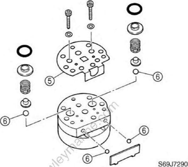
- Remove the bracket (5), then the balls (6).
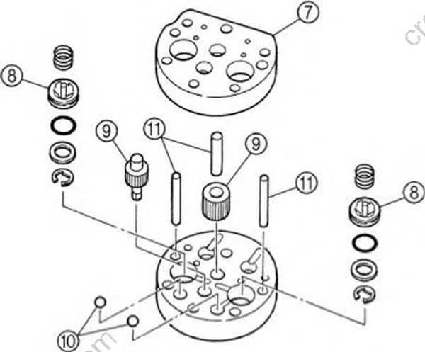
Remove the gear housing 2 (7), then the shuttle pistons (8).
Remove the drive gear (9), balls (10), and dowel pins (11).
Disassembling the tilt cylinder and trim cylinders
Hold the tilt cylinder (1) in a vise using aluminum plates (a) on both sides.
Loosen the tilt cylinder end screw (2) and then remove the tilt piston assembly.
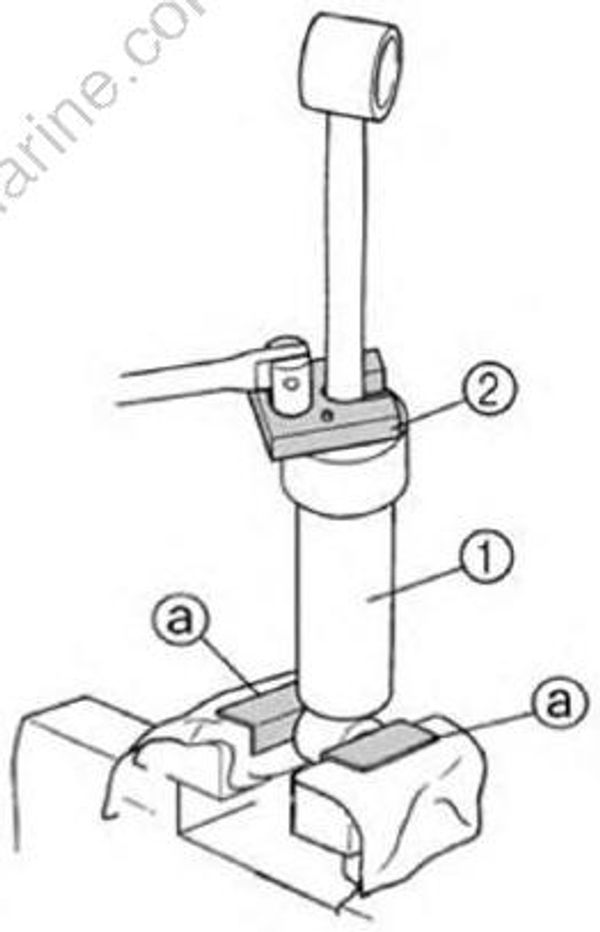
Make sure that the rams are fully extended before removing the end screw.
Trim and tilt cylinder wrench: YB-06175-2B
Drain the power trim and tilt fluid.
Remove the free piston (3), and then blow compressed air through the hole (b) while holding down the cloth.
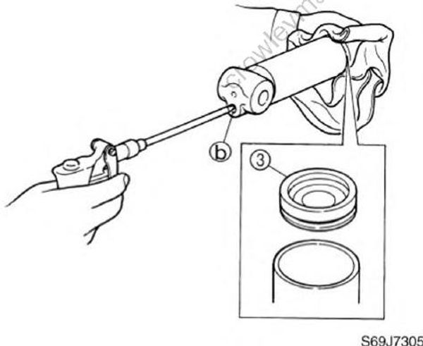
Never look into the tilt cylinder opening because the free piston and power trim and tilt fluid may be expelled out force fully.
Hold the tilt piston in a vise using the special service tool (4) on both sides.
Remove the tilt ram.
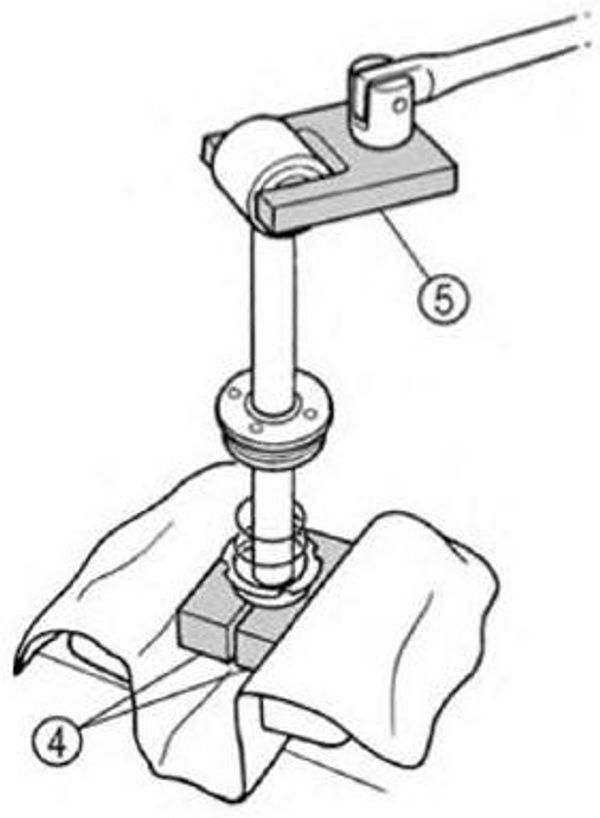
PTT piston vice attachment (4): YB-06572
Tilt rod wrench (5): YB-06569
- Hold the cylinder block (6) in a vise using aluminum plates (a) on both sides.
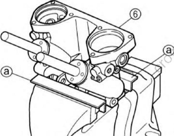
- Loosen the trim cylinder end screws (7), and then remove them.
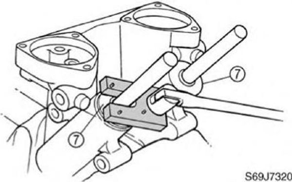
Trim and tilt cylinder wrench: YB-06175-2B
Remove the trim piston assemblies.
Drain the power trim and tilt fluid.
Remove the circlip (8), adapter (9), and spring © from the trim piston assemblies.
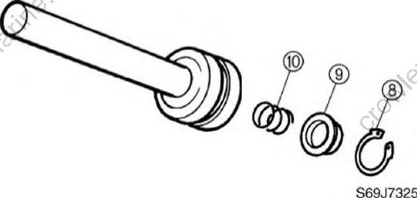
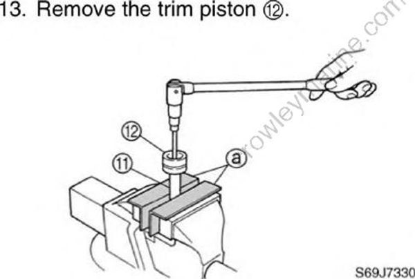
Hold the trim ram (11) in a vise using aluminum plates (a) on both sides.
Remove the trim piston (12).
Checking the reservoir
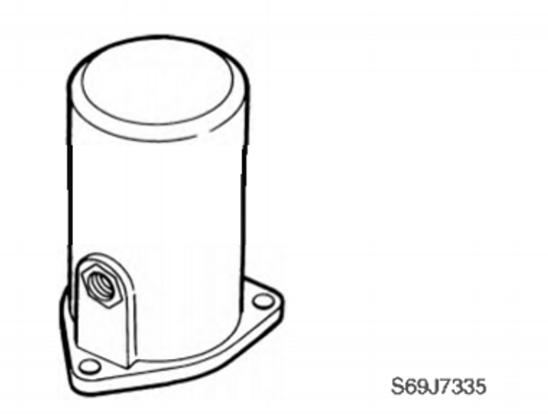
- Check the reservoir for cracks or corrosion. Replace if necessary.
Checking the tilt cylinder and trim cylinder
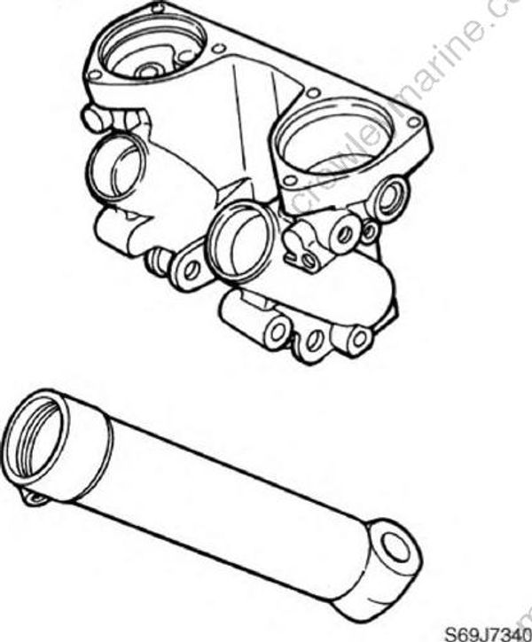
Check the power trim and tilt unit for cracks or corrosion. Replace if necessary.
Check the inner walls of the cylinder block and tilt cylinder for scratches. Replace if necessary.
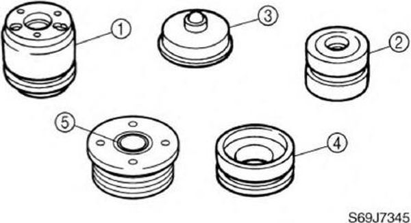
- Check the outer surface of the tilt piston (1) , trim piston (2), adapter (3) free piston (4), and oil seal of end screw (5) for scratches. Replace if necessary.
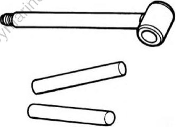
- Check the trim and tilt rams for bends or excessive corrosion. Polish with #400 600 grit sandpaper if there is light rust or replace if necessary.
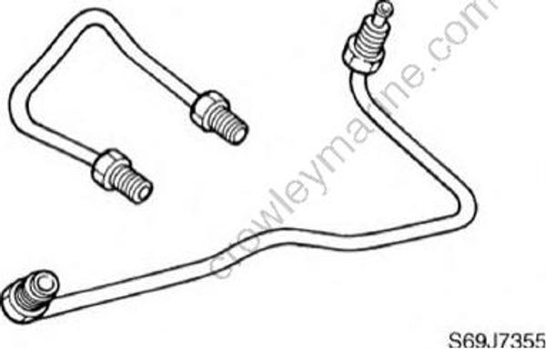
- Check the pipes for cracks or corrosion. Replace if necessary.
Checking the valves
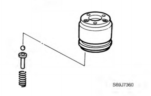
- Check the operation of the tilt piston absorber valves and the valves for dirt or residue. Clean if necessary.
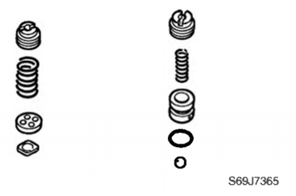
- Check the up-relief valve and down-relief valve for dirt or residue. Clean if necessary.
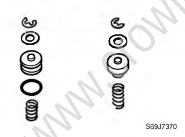
- Check the main valves for dirt or residue. Clean if necessary.
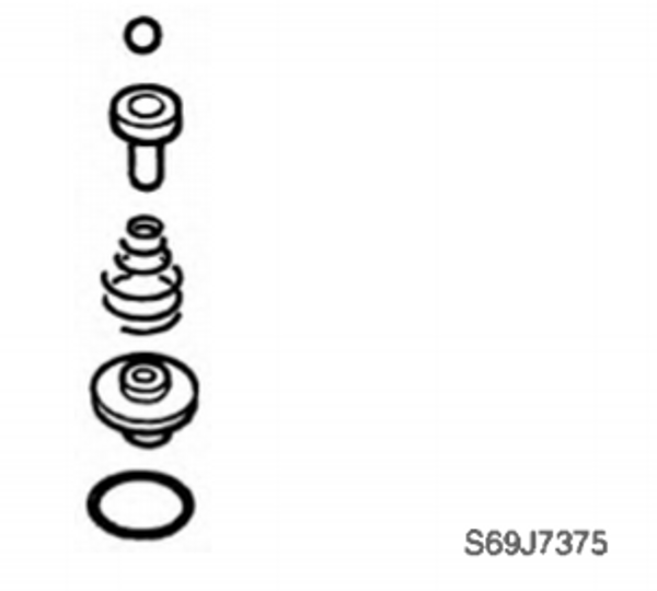
- Check the absorber valves for dirt or residue. Clean if necessary.
Checking the filters
Checking the filters
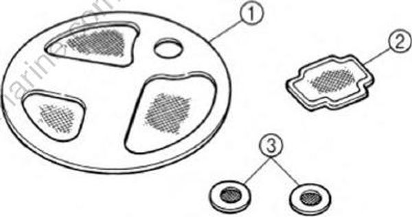
- Check gear pump filters (1) and (2) shuttle piston filters (3) for dirt or residue. Clean if necessary.
Checking the gear pump
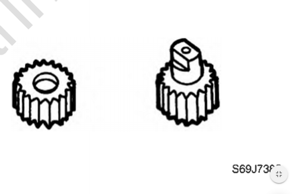
- Check the drive gear for damage or excessive wear. Replace if necessary.
Checking the gear pump housing
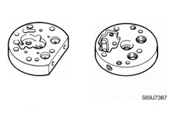
- Check the gear pump housing for scratches. Replace if necessary.
Assembling the gear pump
Install the drive gears (1), dowel pins (2), balls (3) and shuttle pistons (4) into the gear housing 1 (5).
Install the gear housing 2 (6).
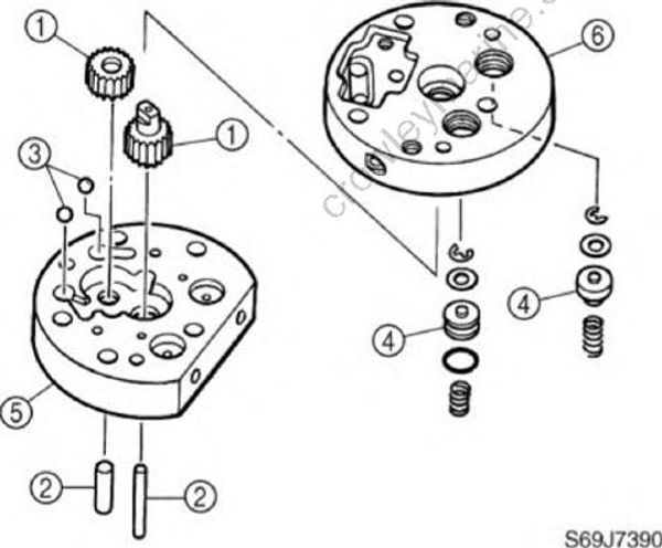
- Install the balls (7), manual release spring (8), and bracket (9) by installing the bolts (10), then tightening them to the specified torque.
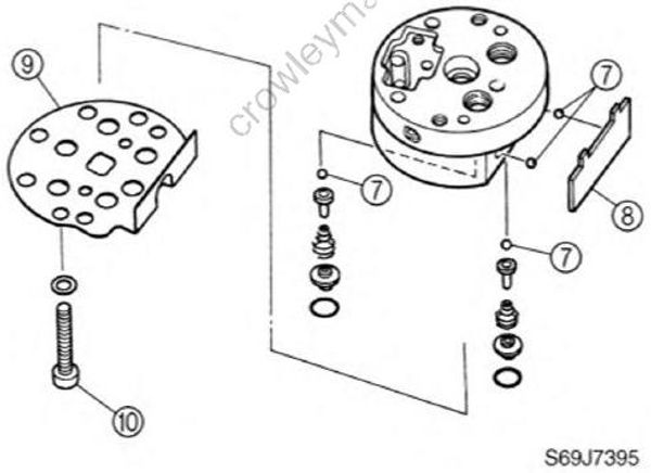
Gear pump bracket bolt (10): 7 N⋅m (0.7 kgf⋅m, 5.1 ft⋅lb)
- Install the relief valve seal (11) and ball (12) into the gear housing 1 (15).
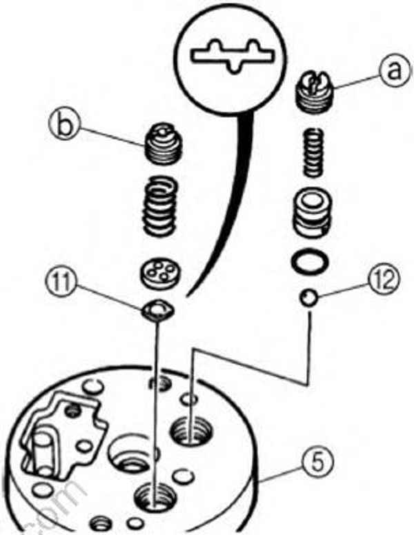
Up-relief lock screw (a) height
(from the top of the gear housing): 1.8-2.0 mm (0.071-0.079 in) Down-relief lock screw (b) depth (from the top of the gear housing): 1.5-2.0 mm (0.059-0.079 in)
Install the filters (13) and gear pump (14) by installing the bolts (15), then tightening them to the specified torque.
Install the manual valve (16).
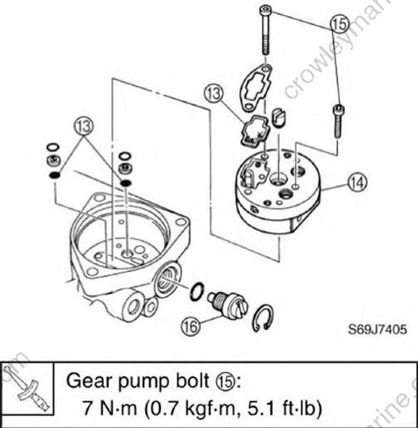
Gear pump bolt (15): 7Nm (0.7 kgfm , 5.1 ftlb)
Assembling the tilt ram
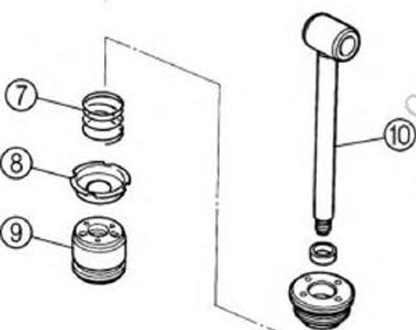
- Install the new dust seal (1), O-rings (2) and (3), and backup ring (4) into the tilt cylinder end screw (5).
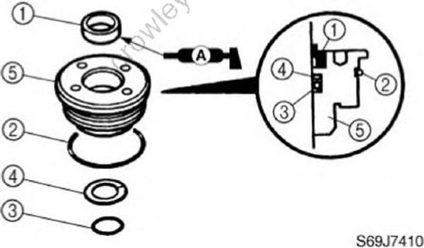
- Install the tilt cylinder end screw (6), spring (7), adapter (8), and tilt piston (9) to the tilt ram (5).
Hold the tilt piston in a vise using the special service tool (11) on both sides.
Tighten the tilt ram (10) to the specified torque.
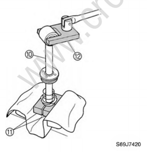
PTT piston vice attachment (11): YB-06572
Tilt rod wrench (12): YB-06569
Tilt ram (10):55 N⋅m (5.5 kgf⋅m, 40 ft⋅lb)
Install the new O-ring (13) and backup ring (14) into the tilt piston (9).
Install the balls (15), absorber valve pins (16), and springs (17) as shown.
Install the washers (18), plate (19), and bolt (20) to the tilt piston (9), and then tighten the bolt to the specified torque.
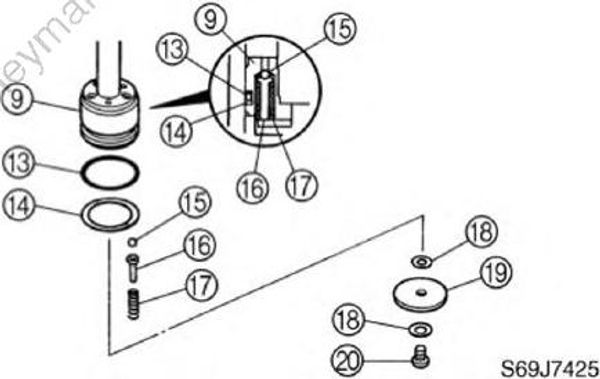
Tilt piston bolt: 7 N⋅m (0.7 kgf⋅m, 5.1 ft⋅lb)
Assembling the trim rams
- Install the trim piston (1) to the trim ram (2).
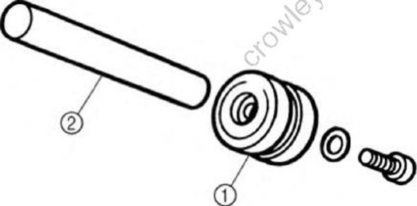
Hold the trim ram (2) in a vise using aluminum plates (a) on both sides.
Tighten the trim piston bolt to the specified torque.
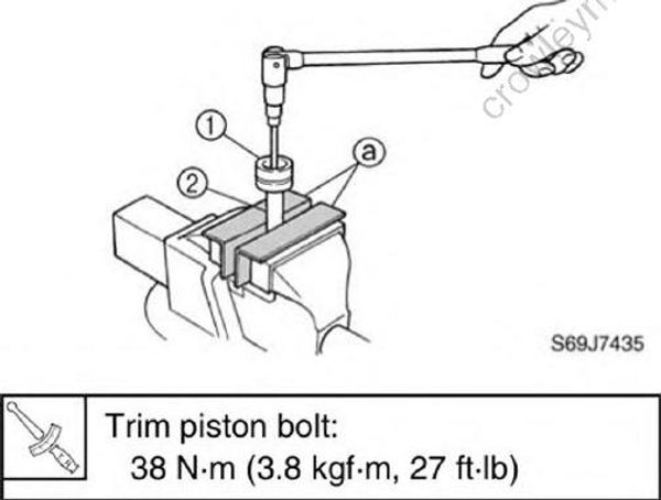
Trim piston bolt: 38 N⋅m (3.8 kgf⋅m, 27 ft⋅lb)
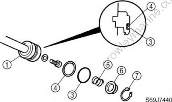
- Install the new O-ring (3), backup ring (4), spring (5), adapter (6), and circlip (7) to the trim piston (1).
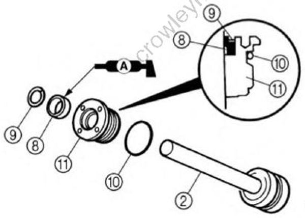
Install the new oil seal (8), circlip (9), and new O-ring (10) into the trim cylinder end screw (11).
Install the trim cylinder end screw (12) into the trim ram (2).
Installing the tilt cylinder
Install the new O-ring (1) to the free piston (2).
Push the free piston (2) into the tilt cylinder (3) until it bottoms out.
Install the tilt cylinder (3) to the cylinder block (4).
Install pipes (5) and (6), and then tighten them to the specified torque.
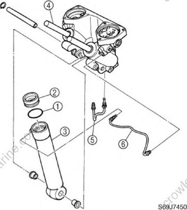
Pipe joint (5) and (6): 15 N⋅m (1.5 kgf⋅m, 11 ft⋅lb)
Installing the trim rams
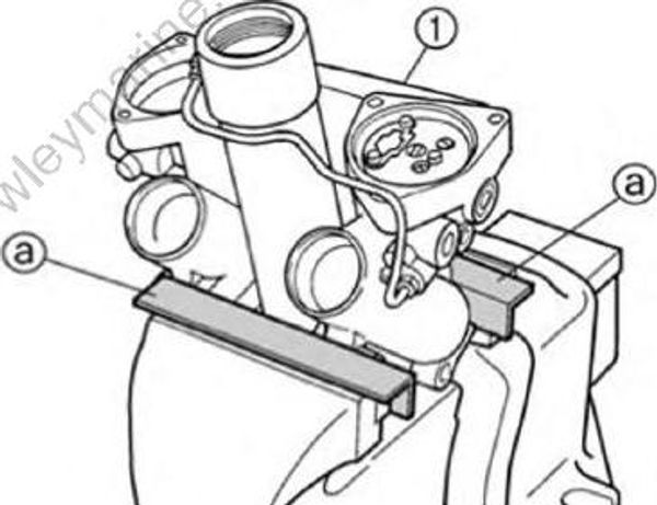
- Hold the cylinder block (1) in a vise using aluminum plates (a) on both sides.
- Fill the trim cylinders with the recommended fluid to the correct level (b) as shown.
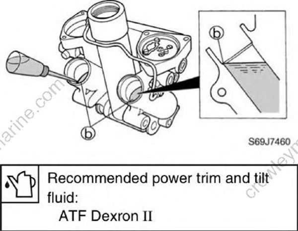
Recommended power trim and tilt fluid: ATF Dexron II
- Install the trim piston assembly into the trim cylinder, and then tighten the trim cylinder end screw (2) to the specified torque.
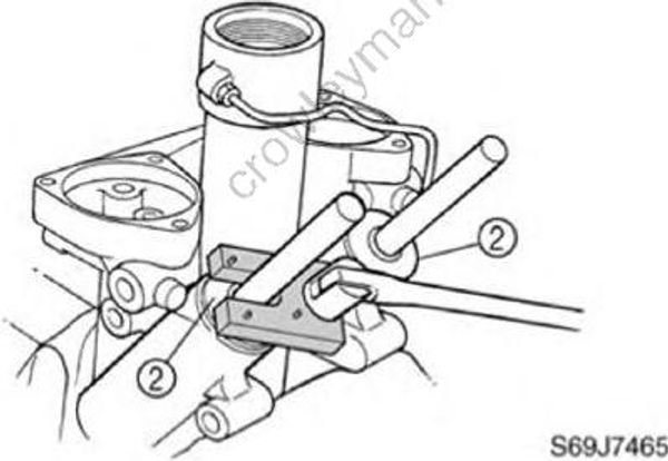
Do not push the trim rams down while installing them into the trim cylinders. Otherwise, the power trim and tilt fluid may spurt out from the unit
Trim and tilt cylinder wrench: YB-06175-2B
Trim cylinder end screw (2): 160 N⋅m (16 kgf⋅m, 115 ft⋅lb)
Installing the power trim and tilt motor
- Install the joint (1) into the pump housing.
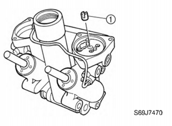
- Fill the pump housing with the recommended fluid to the correct level (a) as shown.
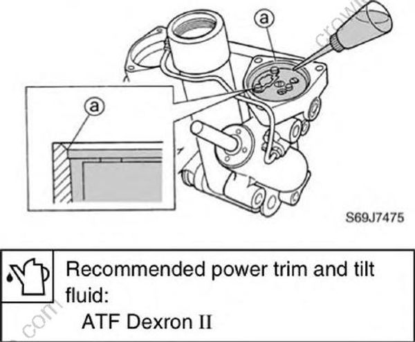
Recommended power trim and tilt fluid: ATF Dexron II
- Remove all of the air bubbles with a syringe or suitable tool.
Turn the joint with a screwdriver, and then remove any air between the pump gear teeth.
- Install the new O-ring (2), power trim and tilt motor (3), and then tighten the bolts (4) to the specified torque.
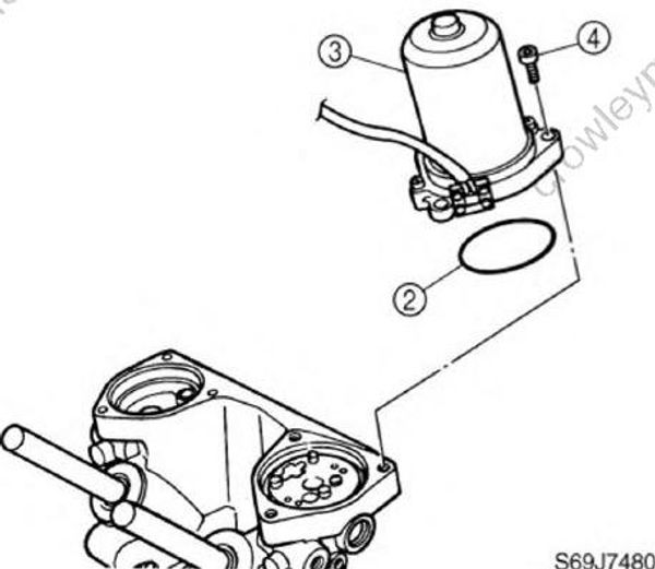
Align the armature shaft with the recess in the joint.
PTT motor bolt : 18 Nm (1.8 kgf⋅m, 13 ft⋅lb)
Installing the reservoir
Install the spacer (1), filter (2) and sheet (3) to the cylinder block.
Install the new O-ring (4) and reservoir (5), and then tighten the bolts (6) to the specified torque.
Install the reservoir cap (7), and then tighten it to the specified torque.
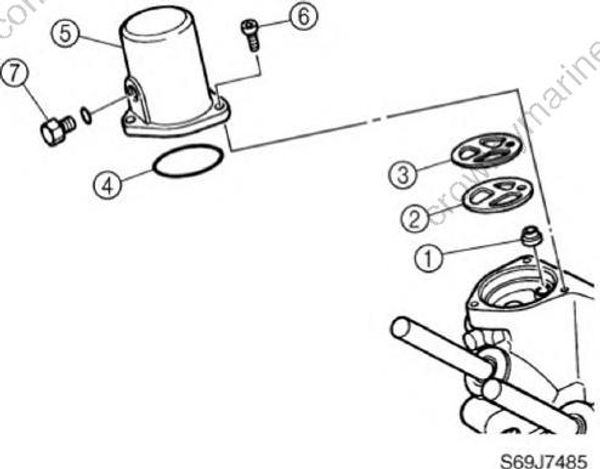
Reservoir bolt (6): 18 Nm (1.8 kgf⋅m, 13 ft⋅lb)
Reservoir cap (7): 7 N⋅m (0.7 kgf⋅m, 5.1 ft⋅lb)
Installing the tilt ram
Fill the tilt cylinder with the recommended fluid to the correct level (a) as shown.
Add a small amount of the recommended fluid through the cylinder block hole (b) as shown.
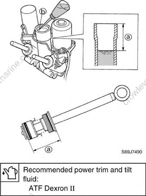
Recommended power trim and tilt fluid: ATF Dexron II
- Install the tilt piston assembly into the tilt cylinder, and then tighten the tilt cylinder end screw (1) to the specified torque.
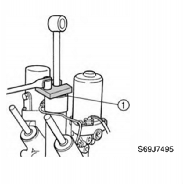
To prevent the power trim and tilt fluid from spurting out due to internal pressure, the tilt ram should be kept at full length.
Place the tilt cylinder end screw at the bottom of the tilt ram and install the tilt piston assembly into the tilt cylinder.
Trim and tilt cylinder wrench: YB-06175-2B
Trim cylinder end screw: 90 N⋅m (9.0 kgf⋅m, 65 ft⋅lb)
Bleeding the power trim and tilt unit
Not installed
- Tighten the manual valve (1) by turning it clockwise.
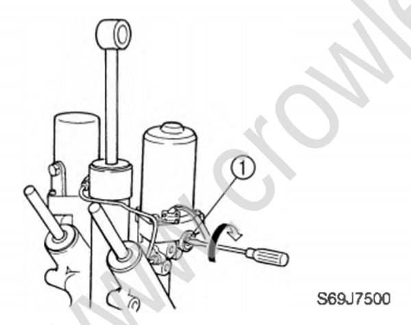
Place the power trim and tilt unit in an upright position.
Check the fluid level in the reservoir.
The fluid level should be at the brim of the filler hole.
- If necessary, add sufficient fluid of the recommended type to the correct level.
Recommended power trim and tilt fluid: ATF Dexron II
Install the reservoir cap.
Connect the PTT motor leads (2) to the battery terminals.
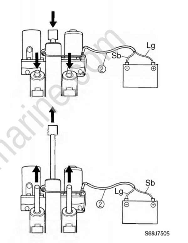
| Ram | PTT motor lead | Battery terminal |
|---|---|---|
| Up | Sky blue (Sb) | (+) |
| Up | Light green (Lg) | (-) |
| Down | Light green (Lg) | (+) |
| Down | Sky blue (Sb) | (-) |
- Reverse the PTT motor leads between the battery terminals to fully extend the tilt ram and trim rams, and then reverse them again to fully retract the rams.
