

POWER TRIM AND TILT (PTT) UNIT
EXPLODED DIAGRAM

REMOVAL AND INSTALLATION CHART
| Step | Procedure/Part name | Q'ty | Service points |
|---|---|---|---|
| PTT UNIT REMOVAL | Follow the left "Step" for removal. | ||
| Tilt up the outboard | NOTE: Turn the tilt support lever (a) towards the clamp bracket and support the outboard. | ||
| 1 | PTT motor lead | 2 | |
| 2 | Plastic band | 2 | |
| 3 | Ground lead | 2 |
EXPLODED DIAGRAM
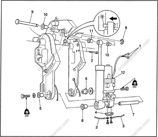
| Step | Procedure/Part name | Q'ty | Service points |
|---|---|---|---|
| 4 | Anode | 1 | |
| 5 | Shaft | 1 | |
| 6 | Bushing | 2 | |
| 7 | Bushing | 1 | |
| 8 | Circlip | 1 | |
| 9 | Shaft pin | 1 | |
| 10 | Bushing | 2 | |
| 11 | Bushing | 1 | |
| 12 | PTT unit | 1 |
Reverse the removal steps for installation.
