Electrical component (multifunction)
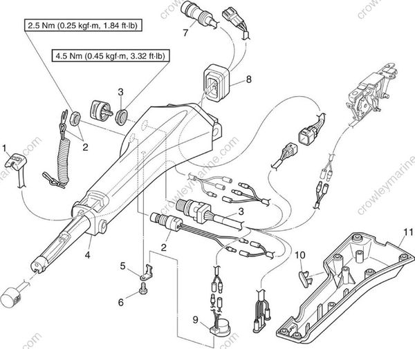
| No. | Part name | Q’ty | Remarks |
|---|---|---|---|
| 1 | Cap | 1 | |
| 2 | Engine shut-off switch | 1 | M16 |
| 3 | Engine start switch | 1 | M20 |
| 4 | Tiller handle | 1 | |
| 5 | Bracket | 1 | |
| 6 | Bolt | 1 | M6 x 15 mm |
| 7 | Extension wiring harness | 1 | |
| 8 | Grommet | 1 | |
| 9 | Buzzer | 1 | |
| 10 | Cap | 1 | |
| 11 | Cover | 1 |
Disassembling the electrical component (multifunction)
Remove the buzzer “1”, and then disconnect the buzzer connectors “a” and engine shut-off switch connectors “b”.
Remove the engine shut-off switch “2”.
Disconnect the engine start switch coupler “c”.
Remove the extension wiring harness “3”, trolling switch “4”, and grommet “5”.
Remove the engine start switch “6”.

Assembling the electrical component (multifunction)
Install the engine start switch “1” so that the hole “a” is facing up, and then tighten the start switch nut “2” to the specified torque.
Pass the extension wiring harness “3”, and trolling switch lead “4” through the grommet “5”, and then install it.
Install the engine shut-off switch “6”, and then tighten the engine shut-off switch nut “7” to the specified torque.
Install the buzzer “8”, and then connect the engine shut-off switch connectors “b” and the buzzer connectors “c”.
Connect the engine start switch coupler “d”.

Engine start switch nut “2” : 4.5 Nm (0.45 kgf•m, 3.32 ft•lb)
Engine shut-off switch nut “7” : 2.5 Nm (0.25 kgf•m, 1.84 ft•lb)
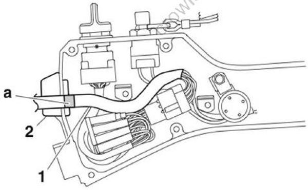
- Align the blue tape “a” on the extension wiring harness “1” with the inner end of the grommet “2”.