

EXPLODED DIAGRAM
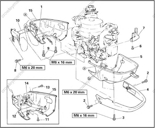
REMOVAL AND INSTALLATION CHART
| Step | Procedure/Part name | Q'ty | Service points |
|---|---|---|---|
| CARRYING HANDLE AND BOTTOM COWLING REMOVAL | Follow the left "Step" for removal. | ||
| Top cowling | |||
| Choke wire | Refer to "INTAKE SYSTEM" in chapter 4. | ||
| 1 | Engine stop switch lead | 1 | !NOTE! After installation, clamp the engine stop switch lead to part 2 using the lead clamp(a) |
| 2 | Bolt with washer (carrying handle 2) | 4 | |
| 3 | Bolt with washer (bottom cowling 2) | 3 | |
| 4 | Carrying handle 2 (protector) | 1 | |
| 5 | Bottom cowling 2 | 1 | !NOTE! Clamp the hi-tension cord using the cord clamp (£), after the bottom cowling 2 has been fitted. |
EXPLODED DIAGRAM

| Step | Procedure/Part name | Q'ty | Service points |
|---|---|---|---|
| 6 | Screw (shift lever) | 1 | |
| 7 | Shift lever | 1 | |
| 8 | Bolt with washer (carrying handle 1) | 4 | |
| 9 | Bolt with washer (bottom cowling 1) | 3 | |
| 10 | Carrying handle 1 ass'y | 1 | |
| 11 | Screw | 1 | |
| 12 | Fuel cock ass'y | 1 | |
| 13 | Bolt with washer | 1 | |
| 14 | Fuel joint ass'y | 1 | |
| 15 | Bottom cowling 1 ass'y | 1 | |
| Reverse the removal steps for installation. |
