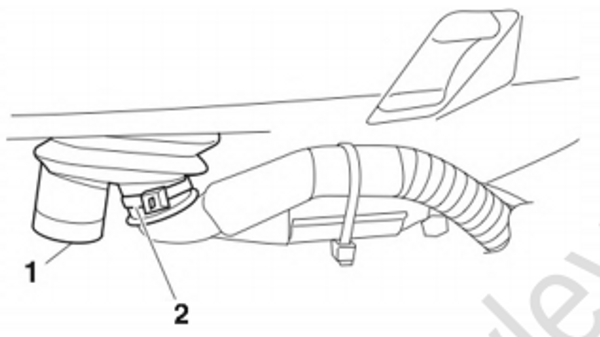
Bottom cowling
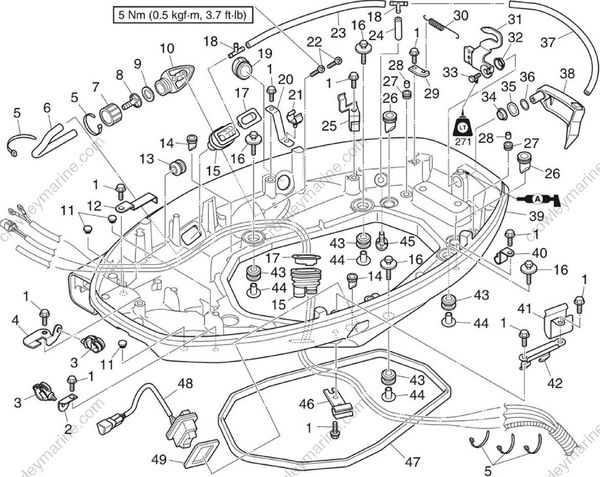
| No. | Part name | Q’ty | Remarks |
|---|---|---|---|
| 1 | Bolt | 10 | M6 x 20 mm |
| 2 | Bracket | 1 | |
| 3 | Holder | 2 | |
| 4 | Bracket | 1 | |
| 5 | Plastic tie | 5 | |
| 6 | Hose | 1 | Hose joint to hose joint |
| 7 | Hose joint | 1 | |
| 8 | Hose joint | 1 | |
| 9 | Gasket | 1 | |
| 10 | Adapter | 1 | |
| 11 | Grommet | 3 | |
| 12 | Plate | 1 | |
| 13 | Grommet | 1 | |
| 14 | Grommet | 2 | |
| 15 | Grommet | 2 | |
| 16 | Bolt | 4 | M6 x 30 mm |
| 17 | Guide | 2 |
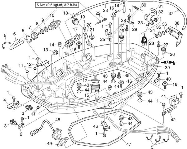
| No. | Part name | Q’ty | Remarks |
|---|---|---|---|
| 18 | Hose joint | 2 | |
| 19 | Grommet | 1 | |
| 20 | Bracket | 1 | |
| 21 | Holder | 1 | |
| 22 | Screw | 2 | Not reusable |
| 23 | Hose | 1 | |
| 24 | Hose | 1 | Not reusable |
| 25 | Holder | 1 | |
| 26 | Grommet | 2 | M6 x 35 mm |
| 27 | Grommet | 2 | Not reusable |
| 28 | Collar | 2 | EX |
| 29 | Hook | 1 | M6 x 20 mm |
| 30 | Spring | 1 | IN |
| 31 | Lever | 1 | |
| 32 | Bushing | 1 | M6 x 16 mm |
| 33 | Bolt | 2 | |
| 34 | Bushing | 4 | M6 x 25 mm |
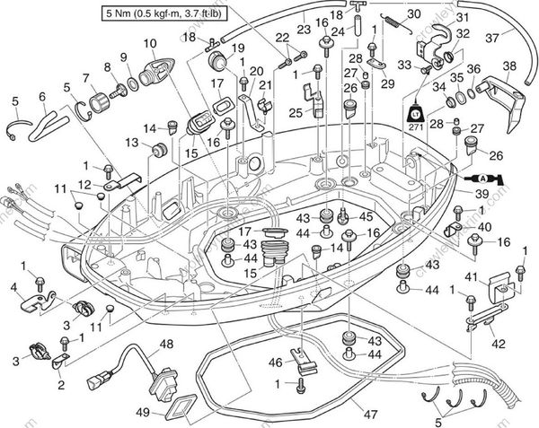
| No. | Part name | Q’ty | Remarks |
|---|---|---|---|
| 35 | Wave washer | 1 | |
| 36 | Washer | 1 | |
| 37 | Hose | 1 | Exhaust cover to hose joint |
| 38 | Cowling lock lever | 1 | |
| 39 | Bottom cowling | 1 | |
| 40 | Holder | 1 | |
| 41 | Holder | 1 | |
| 42 | Holder | 1 | |
| 43 | Grommet | 4 | |
| 44 | Collar | 4 | |
| 45 | Water outlet | 1 | |
| 46 | Holder | 1 | |
| 47 | Rubber seal | 1 | Not reusable |
| 48 | PTT switch | 1 | |
| 49 | Gasket | 1 | Not reusable |
Disassembling the bottom cowling
Remove the guide “1".
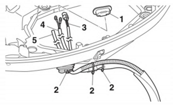
Remove the plastic ties “2”, and then remove the trim sensor lead “3”, PTT motor lead “4”, and speedometer hose "5"
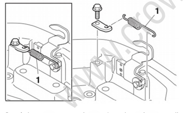
- Remove the spring "1"
{{IMAGE_2}}
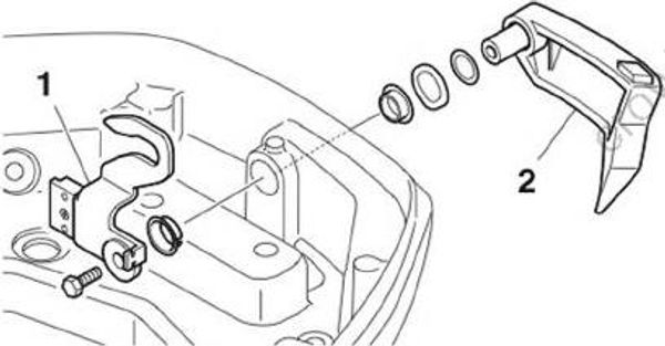
- Remove the lever “1” and cowling lock lever “2”.
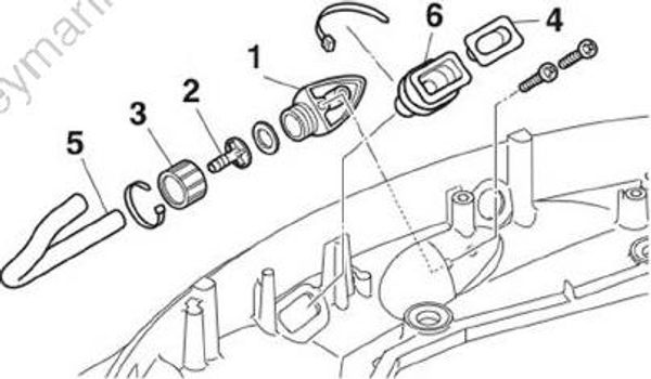
Remove the flushing hose adapter “1” and hose joints “2” and “3”.
Remove the guide “4”, flushing hose “5”, and grommet “6”
Assembling the bottom cowling
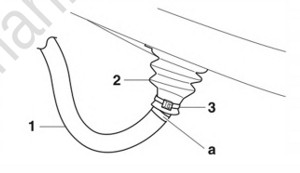
- Route the flushing hose “1” through the grommet “2”, and then fasten the grommet “2” using the plastic tie “3”.
TIP:
Align the white paint mark “a” on the flushing hose “1” with the outer end of the grommet "2".
- Install the guide “1”.
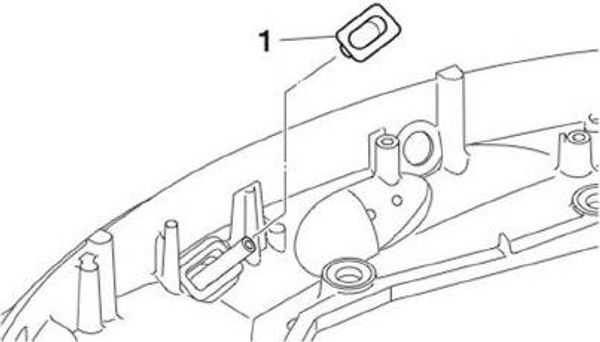
Install the flushing hose adapter “1”, and then tighten the flushing hose adapter screws “2” to the specified torque.
Route the flushing hose “3” through the hose joint “4”, install it to the hose joint “5”, and then fasten the flushing hose “3” using the plastic tie “6”.
Install the hose joint to the adapter “1” along with the gasket “7”.
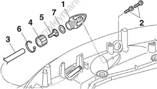
Flushing hose adapter screw “2”: 5 Nm (0.5 kgf-m, 3.7 ft-lb)
- Install the cowling lock lever “1” and lever “2”.
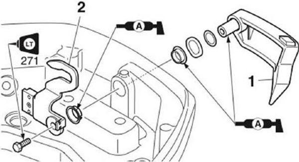
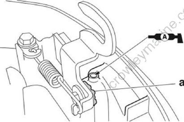
- Install the spring "1".
- Inject grease into the housing until grease comes out from the housing “a”.
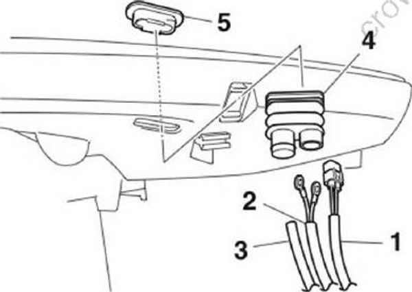
- Route the trim sensor lead “1”, PTT motor lead “2”, and speedometer hose “3” through the grommet “4”, and then install the grommet “4” and guide “5” to the bottom cowling.
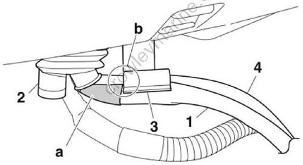
- Align the gray tape “a” on the PTT motor lead “1” with the outer end of the grommet “2” and the end “b” of the holder “3”. Install the trim sensor lead “4” and the PTT motor lead “1” to the holder “3”.
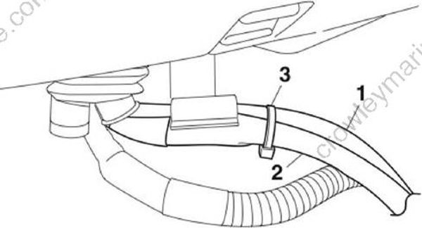
- Fasten the trim sensor lead “1” and the PTT motor lead “2” using the plastic tie “3”.
- Fasten the speedometer hose “1” and the holder “2” using the plastic tie “3”.
TIP:
Fasten the speedometer hose “1” at the middle of the white tape “a” using the plastic tie "3"
![][107216]
- Fasten the grommet “1” using the plastic tie “2”.