

Preface
This kit converts 1998 and newer 5/6 4-Stroke Evinrude® outboards to remote controlled.
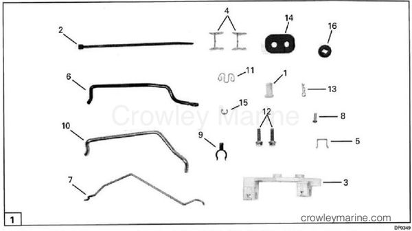
[1]
Contents of Kit
| Ref. | P/N | Name of Part | Qty |
|---|---|---|---|
| 1 | 310525 | Pin, Clevis | 1 |
| 2 | 320107 | Tie Strap | 1 |
| 3 | 441251 | Bracket | 1 |
| 4 | 441252 | Retainer, Cable | 2 |
| 5 | 441253 | Clamp | 1 |
| 6 | 441254 | Link, Shift | 1 |
| 7 | 441255 | Link, Choke | 1 |
| 8 | 441256 | Pin | 1 |
| 9 | 441258 | Holder | 1 |
| 10 | 441327 | Link, Shift | 1 |
| 11 | 441329 | Retainer | 1 |
| 12 | 446099 | Screw, M6x1x20 | 2 |
| 13 | 446162 | Pin, Snap | 1 |
| 14 | 446252 | Grommet, Shift & Throttle | 1 |
| 15 | 446375 | Retainer | 1 |
| 16 | 446431 | Grommet, Choke | 1 |
Installation of this kit involves procedures in BRP Service Manual and BRP Outboard Remote Control Installation Instructions.
To prevent accidental starting, twist and remove the spark plug lead.
The kit can be installed with the lower engine covers in place. Removal of engine covers to install this kit is recommended.

[2]
1. Remove choke lever (A), choke link (B), and grommet (C) from the port lower engine cover. Remove grommet (D), from lower engine cover.
Retain the choke lever and discard the choke link and grommets.
[3]
2. Remove throttle cable anchor screw (E) and extension (F) and discard.
[4] [5]
3. Remove throttle lever shoulder screw (G) and washer (H). Disconnect the throttle cable from the throttle lever.
[6]
4. Remove the retainer (I) from the shift lever (J) and discard. Remove the shift handle link (K) from the shift lever.
[7]
5. Remove retainer (L), pin (M), and shift handle assembly (N) from the steering bracket assembly.

[8]
6. Reroute the throttle cable to the starboard side of the engine and retain in the position shown with tie strap (2).
2000 and Newer
[9]
7. Snap holder (9) into bracket (3).
[10]
8. Using screws (12), install bracket onto the engine.
All Models
[11]
9. Route the remote control throttle cable through the cable opening on the port lower engine cover.
[11]
10. Attach cable casing guide to the inside of the throttle lever with throttle clevis pin (1) and throttle snap pin
(13). Install washer (A), throttle lever, and secure with shoulder screw (B). Torque shoulder screw to 48-96 in. lbs. (5,4-10,8 Nm).
[11]
11. Pull firmly on throttle cable to remove backlash. Install trunnion nut in anchor pocket.
[12]
12. Adjust trunnion nut so that carburetor throttle plate lever closes completely to the idle stop screw.

[13]
13. Advance remote control handle to wide-open-throttle position. Loosen throttle stop screw nut (C). Adjust stop screw (D) against the throttle cable lever to maintain the throttle plate in the wide-open-throttle position. Tighten stop screw nut after adjustment is correct.
14. Check cable adjustment:
If throttle cable adjustment is too loose, idle speed might be high and inconsistent.
If throttle cable adjustment is too tight, control effort might be high through the shifting range.
[14]
15. Snap throttle cable retainer (4) into position until locked.
16. Move the remote control handle to NEUTRAL.
Before connecting shift cable, verify control handle position and neutral lockout index plate orientation.
17. Rotate the propeller shaft and shift gearcase into NEUTRAL.

[15]
18. Route the remote control shift cable through the cable opening. Pull firmly on shift cable to remove backlash and install shift cable trunnion nut in anchor pocket, and secure with cable retainer (4).
[16]
19. Install shift link retainer (15) in groove of shift link (6) (10).
[17]
20. Attach shift link (6) (10) into hole of casing guide in shift cable.
[17]
21. Place cable casing guide into shift cable guide holder (A) and route shift link (6) (10) to the shift lever.
98 and 99 Models
[18] [19]
22.Insert shift pin (8). Secure cable with shift clamp (5)
2000 and Newer
[20]
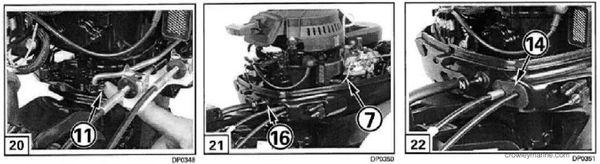
23. Insert shift link into the shift lever. Secure shift link with retainer (11).
All Models
24. If removed, install lower engine covers as described in Section 4 of the service manual.
[21]
25. Install choke grommet (16). Attach choke link (7) to choke shaft on carburetor and connect the other end to the choke lever.
[22]
26. Install shift and throttle cable grommet (14) into opening of lower engine cover.
27. Follow the complete adjustment procedure as outlined in the service manual and remote control installation instructions.
28. Inspect installation to insure that the control cables are attached to the proper engine levers by lifting the fast idle lever to the START position. If correctly attached, the throttle cable and engine throttle lever will move.