

INSTALLATION INSTRUCTIONS
Description:Kit, handle
Part Number: 63001-94J00-0EP
Applications: DF9.9/15 9.9/15 9.9/15
Installation Time:1.5HR
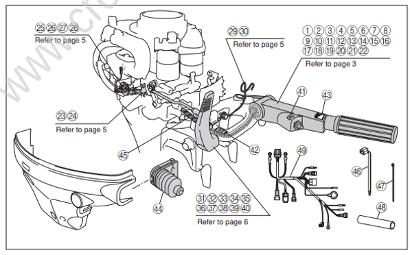
Contents
| Ref. | Part Number | Description | QTY |
|---|---|---|---|
| 1 | 63111-94J00-0EP | Handle, tiller | 1 |
| 2 | 63115-94J00 | Bush, tiller handle | 2 |
| 3 | 63116-94J00 | Rubber, tiller handle friction | 1 |
| 4 | 63121-94J00-0EP | Cover, tiller handle | 1 |
| 5 | 63210-91J00 | Grip comp, handle | 1 |
| 6 | 63220-94J00 | Rod comp, handle | 1 |
| 7 | 63223-89J00 | Stopper, handle rod | 1 |
| 8 | 63225-94J00 | Plate, handle rod adjuster | 1 |
| 9 | 63225-93200 | Bush, handle rod | 1 |
| 10 | 63240-94J00 | Adjuster set, handle rod | 1 |
| 11 | 63246-91J00 | Nut, handle rod adjuster KNO | 1 |
| 12 | 63610-94J00 | Cable assy, throttle | 2 |
| 13 | 09116-08099 | Bolt, tiller handle cover (L30) | 2 |
| 14 | 09126-06015 | Screw, handle grip | 1 |
| 15 | 09136-05041 | Screw, handle rod adjuster | 2 |
| 16 | 09163-06001 | Washer, handle grip screw | 1 |
| 17 | 09205-03038 | Pin, handle rod | 1 |
| 18 | 09440-12027 | Spring, handle rod | 1 |
| 19 | 37830-94J00 | Switch, emergency & stop | 1 |
| 20 | 09160-12067 | Washer, emergency switch | 1 |
| 21 | 37161-94J00 | Switch, start | 1 |
| 22 | 09159-14014 | Nut, starter switch | 1 |
| 23 | 01550-06167 | Bolt, throttle cable bracket | 1 |
| 24 | 19184-94J00 | Bracket, throttle cable | 1 |
| 25 | 19148-94J00 | Drum, throttle | 1 |
| Ref. | Part Number | Description | QTY |
|---|---|---|---|
| 26 | 19121-94J00 | Lever, throttle control | 1 |
| 27 | 13510-93E10 | Rod comp, throttle | 1 |
| 28 | 19131-95502 | Connector, throttle rod | 1 |
| 29 | 65793-94J00 | Holder, fuel hose | 1 |
| 30 | 09116-08103 | Bolt, fuel hose holder | 2 |
| 31 | 21110-93E03 | Lever comp, clutch | 1 |
| 32 | 23115-93E10 | Link, clutch lever | 1 |
| 33 | 23118-94J00 | Nut, clutch link | 1 |
| 34 | 23312-95320 | Connector, clutch link | 1 |
| 35 | 09209-09007 | Connector, clutch link | 1 |
| 36 | 09111-06064 | Bolt, clutch lever | 1 |
| 37 | 09111-06069 | Bolt, clutch link | 1 |
| 38 | 09160-06082 | Washer, clutch lever | 1 |
| 39 | 09160-08045 | Washer, clutch lever | 1 |
| 40 | 09164-08017 | Washer, clutch lever wave | 1 |
| 41 | 37835-91J00-Y5S | Label, stop | 1 |
| 42 | 21131-94J00 | Mark, clutch | 1 |
| 43 | 69714-94J00 | Mark, engine start | 1 |
| 44 | 67331-94J00 | Grommet, side cover | 1 |
| 45 | 34863-94510 | Tube, throttle cable | 1 |
| 46 | 09407-10404 | Clamp, wiring harness | 2 |
| 47 | 09407-11401 | Clamp, sw lead | 2 |
| 48 | 33833-94J00 | Tube, sw lead | 1 |
| 49 | 36610-94J10 | Harness assy, wiring | 1 |
| 50 | 63119-94J00 | Installation instruction | 1 |
Material
Three bond 1342 to be purchased separately as it is not contained in the kit.
Suzuki water resistance grease to be purchased separately as it is not contained in the kit.
Important
WARNING/CAUTION/NOTE
Please read this manual and follow its instruction carefully. To emphasize special information, the symbol⚠ and the words WARNING, CAUTION and NOTE have special meanings.
These special meanings apply except when laws or regulations require that the signal words be used with a different meaning. Pay special attention to the messages highlighted by these signal words.
Indicates potential hazard that could result in death or injury.
Indicates potential hazard that could result in motor damage.
: Indicates special information to make maintenance easier or instruction clearer.
・ Only an authorized Suzuki outboard motor dealer or a qualified service mechanic should per form installation of this part.
・ Before performing the following procedures, be sure that the throttle/shift cables are installed in the remote control box according to the remote control manufacture’s instructions.
・ Use of an outboard motor with a remote control should not be attempted unless an emergency stop switch is mounted so as to permit attachment of the stop switch lanyard to the boat opera tor.
・ All Suzuki NA27S remote control boxes are equipped with an emergency stop switch feature.
For other applications, an emergency stop switch and mounting hardware are available..
Preparation before Installation
・ The information in this installation instruction is intended for use only by skilled technicians who have the proper tools, equipment and training.
・ These procedures should not be attempted by a customer. ・ The kit must be used for the intended purpose only.
・ Check the parts contained in the kit against the list in the installation instruction and confirm all parts are in the kit.
・ When installing the kit, set the motor on a stable engine hanger with the engine stopped. ・ Please refer to the repair Manual because the below parts need desorption.
- Side covers
- Recoil starter or flywheel cover
- Flywheel
- Wire harness
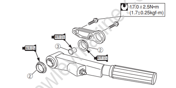
Assemble and installation of tiller handle
| Ref. | Part Number | Description | QTY |
|---|---|---|---|
| 1 | 63111-94J00-0EP | Handle, tiller | 1 |
| 2 | 63115-94J00 | Bush, tiller handle | 2 |
| 3 | 63116-94J00 | Rubber, tiller handle friction | 1 |
| 4 | 63121-94J00-0EP | Cover, tiller handle | 1 |
| 5 | 63210-91J00 | Grip comp, handle | 1 |
| 6 | 63220-94J00 | Rod comp, handle | 1 |
| 7 | 63223-89J00 | Stopper, handle rod | 1 |
| 8 | 63225-94J00 | Plate, handle rod adjuster | 1 |
| 9 | 63225-93200 | Bush, handle rod | 1 |
| 10 | 63240-94J00 | Adjuster set, handle rod | 1 |
| 11 | 63246-91J00 | Nut, handle rod adjuster KNO | 1 |
| 12 | 63610-94J00 | Cable assy, throttle | 2 |
| 13 | 09116-08099 | Bolt, tiller handle cover (L30) | 2 |
| 14 | 09126-06015 | Screw, handle grip | 1 |
| 15 | 09136-05041 | Screw, handle rod adjuster | 2 |
| 16 | 09163-06001 | Washer, handle grip screw | 1 |
| 17 | 09205-03038 | Pin, handle rod | 1 |
| 18 | 09440-12027 | Spring, handle rod | 1 |
| 19 | 37830-94J00 | Switch, emergency & stop | 1 |
| 20 | 09160-12067 | Washer, emergency switch | 1 |
| 21 | 37161-94J00 | Switch, start | 1 |
| 22 | 09159-14014 | Nut, starter switch | 1 |
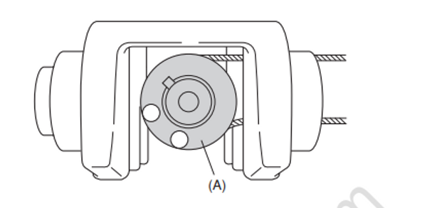
Please be sure the direction of handle rod (A) as below figure when assembling tiller handle.
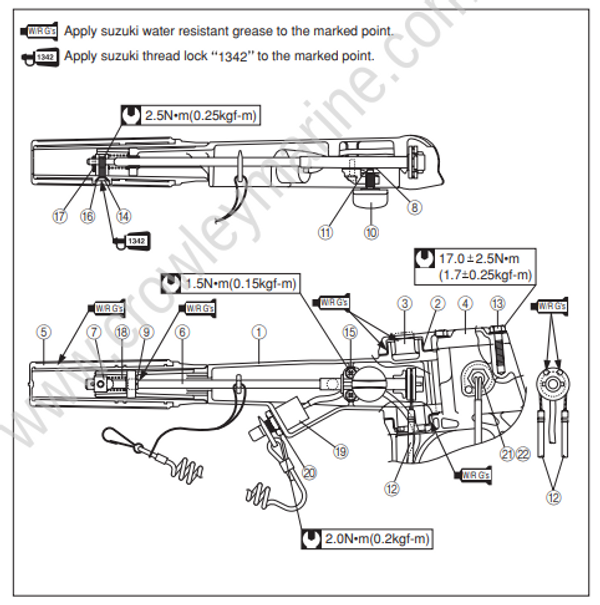
Apply suzuki water resistant grease to the marked point. W/R G’s
Please put the lead wire of emergency stop switch (19), starter switch K and throttle cable B through the pipe of steering bracket as shown below.
And then involve the tube (45) to the wire and cables as shown below.

Installation throttle link
Apply suzuki water resistant grease to the marked point.
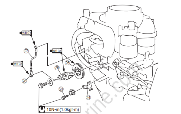
| Ref. | Part Number | Description | QTY |
|---|---|---|---|
| 23 | 01550-06167 | Bolt, throttle cable bracket | 1 |
| 24 | 19184-94J00 | Bracket, throttle cable | 1 |
| 25 | 19148-94J00 | Drum, throttle | 1 |
| 26 | 19121-94J00 | Lever, throttle control | 1 |
| 27 | 13510-93E10 | Rod comp, throttle | 1 |
| 28 | 19131-95502 | Connector, throttle rod | 1. |
Installation fuel hose holder
Please clamp the lead wire of the start switch with the fuel hose holder.

| Ref. | Part Number | Description | QTY |
|---|---|---|---|
| 29 | 65793-94J00 | Holder, fuel hose | 1 |
| 30 | 09116-08103 | Bolt, fuel hose holder | 2. |
Installation clutch lever
Apply suzuki water resistant grease to the marked point.

| Ref. | Part Number | Description | QTY |
|---|---|---|---|
| 31 | 21110-93E03 Lever comp, clutch | 1 | |
| 32 | 23115-93E10 Link, clutch lever | 1 | |
| 33 | 23118-94J00 Nut, clutch link | 1 | |
| 34 | 23312-95320 Connector, clutch link | 1 | |
| 35 | 09209-09007 Connector, clutch link | 1 | |
| 36 | 09111-06064 Bolt, clutch lever | 1 | |
| 37 | 09111-06069 Bolt, clutch link | 1 | |
| 38 | 09160-06082 Washer, clutch lever | 1 | |
| 39 | 09160-08045 Washer, clutch lever | 1 | |
| 40 | 09164-08017 Washer, clutch lever wave | 1. |
Adjustment
Please refer to the below figure when installing a throttle rod (1).

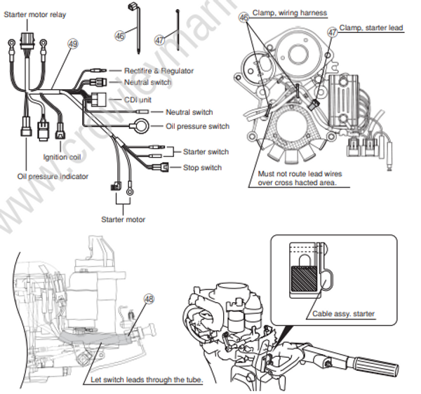
Wire harness
Please fix the wire harness i by using clamp (46), (47) as shown below to prevent any interference.
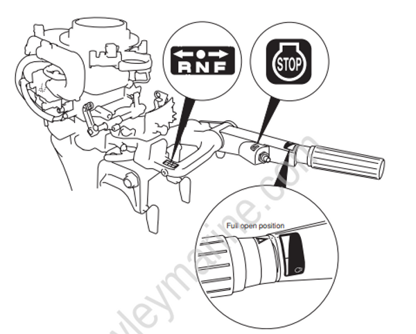
Marking
Always degrease the field which is to be marked as shown below.
Inspection after Installation
1) Inspection without running the engine
• Check control cable ends if there is any inappropriate play and/or loose connection and correct it if necessary.
• While turning the propeller manually until the clutch engages with the gear, move the remote control lever from Neutral to Forward or Reverse position and check throttle operation if it works together with the remote control lever operation. Make sure that the throttle is fully closed when the control lever is in neutral position and the control lever is operated smoothly.
2) Inspection with engine running
• Start the engine and check gear shift and throttle control operation by moving the remote control lever to Forward or Reverse position. Make sure that the engine can be operated reliably.
• While engine is running, operate the emergency stop switch by taking the lock plate off, and confirm the engine stops.
Instruction for Customer
1) Explain the customer to perform the following maintenance periodically.
• Apply Suzuki water resistent grease to the frictional parts, such as throttle cable, throttle lever, throttle drum.
Suzuki water resistant grease is not included in the kit..