

SUZUKI GENUINE ACCESSORIES INSTALLATION INSTRUCTION
| Part NO. | DESCRIPTION | APPLICABLE MODLE |
|---|---|---|
| 34804-94600 | Trim sender kit | DT/90/100/115/140/150/175/200/225 |
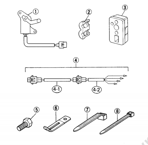
1. COMPONENT PARTS
 ]
]
| Ref NO. | Description | Part NO. | Q'ty |
|---|---|---|---|
| 1 | Sender ass'y,trim | 34801-87D11 | 1 |
| 2 | Grommet, sender lead | 34803-94500 | 1 |
| 3 | Grommet, cable | 34656-94620 | 1 |
| 4 | Trim harness ass'y with adaptor | 36680-92E00 | 1 |
| 4-1 | Trim harness | 36682-E00 | 1 |
| 4-2 | Harness adaptor | 36681-92E00 | 1 |
| 5 | Bolt,trim sender | 09100-06113 | 2 |
| 6 | Clamp sender lead | 09404-06204 | 1 |
| 7 | Cable tie, sender connector | 09407-11401 | 1 |
| 8 | Cable tie, sender lead | 09407-14407 | 2 |
Trim gauge must be purchased separately.
Important
⚠WARNING/⚠CAUTION/NOTE
Please read this manual and follow its instructions carefully.To emphasize special information, the symbol ⚠ and the words WARNING, CAUTION and NOTE have special meaning . Pay special attention to the messages highlighted by these single words.
⚠WARNING indicate a potential hazard that could result in death or injury.
⚠ CAUTION indicate a potential hazard that could result in motor damage.
Indicates special information to make maintenance easier or instructions clearer.
Improper installation of this kit may cause equipment damage.Only your authorized SUZUKI outboard motor dealer or a qualified service mechanic should perform installation of this kit.
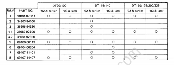
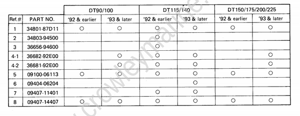
2. MODEL APPLICATION CHART(BY GAUGE STYLE)
a) Kit components for use with 34800-92E00 gauge.
 ]
]
b) Kit components for use with 34800-87D10 gauge.
 ]
]
3. INSTALLATION -TRIM SENDER
Trim sender lead insert the trim sender four pins connector and lead through the hole in the starboard clamp bracket from the inside.
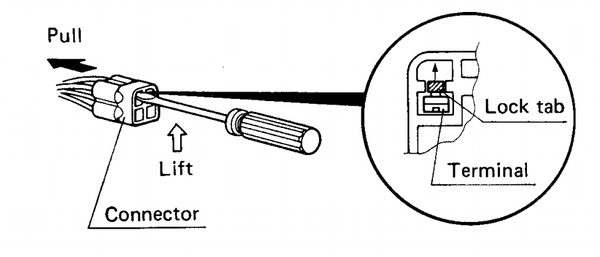
If the connector will not fit through the hole ,it must be removed (Fig.1) and reinstalled
(Fig.2) after the lead is pushed through the hole as shown below.
 ]
]
To remove the connector, lift the lock tab with a small screw driver while lightly pulling out on the lead wire.
 ]
]
To reinstall the connector, insert the terminal back into the connector in the position shown.(be sure the lock tab engages).
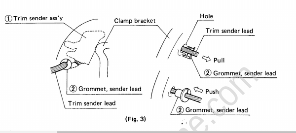
b) Trim sender lead grommet (2) (DT115/140 — ’92 8: earlier models) Pull the lead through until tight and assemble the split grommet (2) to the lead as close to the clamp bracket as possible. Close the grommet and push it into the clamp bracket hole (Fig. 3)
This grommet will not fit the larger clamp bracket hole on ’93 models. Please use clamp (6) in item c) following.
 ]
]
c) Trim sender
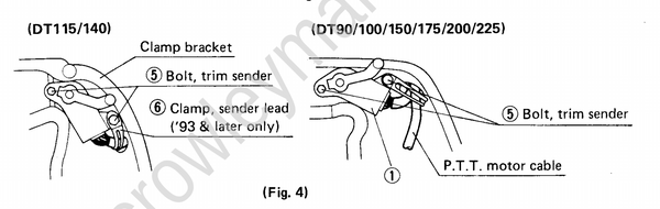
Install the trim sender (1)to the inside or the starboard clamp bracket with bolts (5)(and clamp(6) [DT115/140 — ’93 & later models] ) as shown. (Fig. 4)
 ]
]
d) Cable grommet (DT115/140 — ’92 & earlier models)
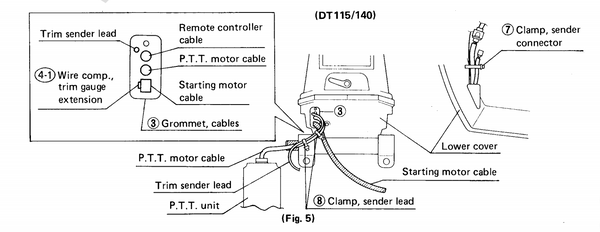
d-1) Remove the original cable grommet from the lower cover and install cable grommet (3). Route
the trim sender lead as shown and secure it with two cable ties (8). Insert the sender lead through the cable grommet at the position indicated and secure it with cable tie (7).
Grommet (3)is standard on ’93 DT1 15/ 140 and therefore does not need to be replaced.
 ]
]
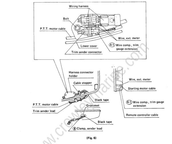
d-2) Route the trim sender lead as shown and secure it with two cable ties (8). Insert the sender lead through the starboard grommet, under the cable stopper and engine connector holder and place
into the connector clip.
lDT90/100/150/175/200/225)
 ]
]
All '92 81 earlier V4/V6 models include a combined monitor/trim harness as standard equipment. On these models, the trim sender and harness connectors should be pressed together before placement into the clip on the connector holder.
4. TRIM SENDER T0 TRIM GAUGE CONNECTIONS
a) Trim gauge ass’y 34800—92E00
a-1) Route the male connector end of trim harness.forward and insert it into the female connec-
tor of the trim gauge.
a-2) Insert the female end of the harness through the cable grommet and connect it to the sender lead connector. On V4/V6 models, route the harness under the cable stopper, press the sender and harness connectors together and place into the clip on the engine connector holder.
 ]
]
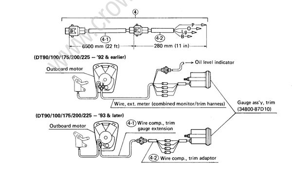
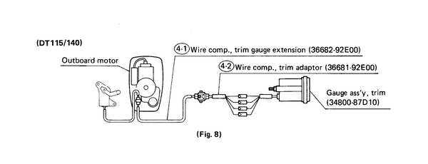
b) Trim gauge ass'y 34800-87D10
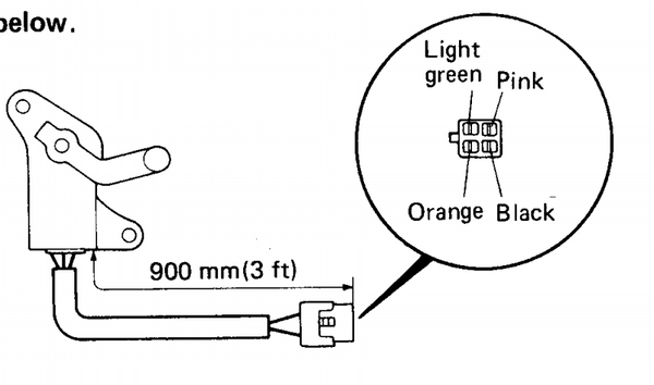
b-1) Route the adaptor end .of the trim harness®(. +.) forward and connect the individual leads (pink, orange, light green 84 black) to the matching color leads of the trim gauge.
b-2) Insert the female and of the trim harness.through the cable grommet and connect it to the
sender lead connector. On V4/V6 models, route the harness under the cable stopper, press the
connectors together and place into the clip on the engine connector holder.
 ]
]
 ]
]
5. VERIFY SENDER AND GAUGE OPERATION AS FOLLOWS:
(1) Turn the ignition switch on and operate the P.T.T. motor down, lowering the engine to the full
trim in (lowest) position. The trim gauge needle should now be on or slightly below the bottom
position indicator bar on the gauge face.
(2) Operate the P.T.T. motor up, raising the engine to the full tilt (highest) position. The trim gauge needle should now be on or slightly above the top position indicator bar on the gauge face.
If the trim gauge does not function or indicates the wrong position, check the following items
and repeat steps (1) and (2) above.
a. Leads and connections
b. Trim gauge power (Gr) and ground (B) supply
c. Sender location/Attachment position
If the trim gauge still does not function or indicates the wrong position, use the following procedure to verify that the trim gauge is functional.
a. Disconnect the trim sender from the trim gauge extension harness at the engine (4 pin connector).
b. Using a jumper wire, connect the black lead terminal to the gray lead terminal in the engine
end of the trim gauge harness connector.
c. Turn the ignition switch on. The trim gauge needle should now be slightly above the top position indicator bar on the gauge face.